Controller and controlling method of switching power supply

a technology of switching power supply and control method, which is applied in the direction of dc-dc conversion, power conversion system, instruments, etc., can solve the problems of increasing power consumption, increasing cost and size of power supply, and deteriorating high-frequency performan

Active Publication Date: 2016-06-02
SILERGY SEMICON TECH (HANGZHOU) CO LTD
View PDF4 Cites 13 Cited by
  • Summary
  • Abstract
  • Description
  • Claims
  • Application Information

AI Technical Summary

Benefits of technology

[0035]In a preferable embodiment, the delay circuit generates a valid ON signal when a predetermined time period has elapsed after the voltage feedback signal crosses zero. The delay circuit maintains a constant delay time to control the moment when the power transistor is turned off, so that the power transistor will be turned on exactly or approximately at a valley bottom. Thus, the conduction loss of the power transistor decreases.

Problems solved by technology

A conventional approach to reduce EMI of the switching power supply is to add an EMI filter into the circuit, which, however, increases cost and size of the power supply, deteriorates high-frequency performance, and increases power consumption.
The frequency jittering control leads to higher conduction loss, and lower system efficiency and higher heat dissipation.
Moreover, because the power transistor is turned on and off at a high voltage, additional electromagnetic radiation may occur, which results in degradation of EMI.

Method used


Image

  • Controller and controlling method of switching power supply
  • Controller and controlling method of switching power supply
  • Controller and controlling method of switching power supply

Examples


first embodiment

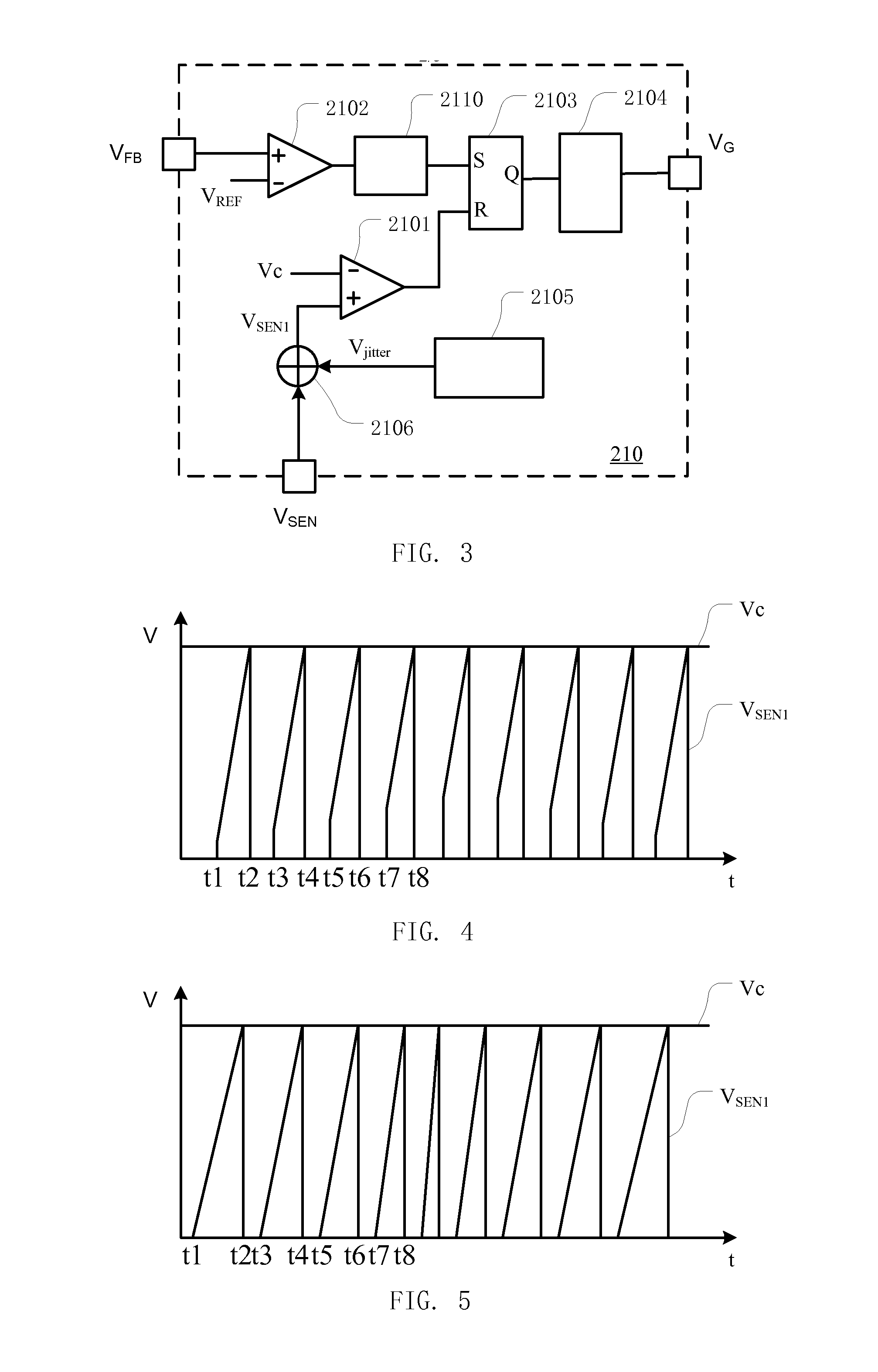
[0099]FIG. 7 is a block diagram of an example frequency-jittering signal generating circuit 2105 of a controller according to the present disclosure.

[0100]The frequency-jittering signal generating circuit 2105 includes a first switch S11 and a first current source I11 which are connected in series between the output terminal and ground, a second switch S21 and a second current source I21 which are connected in series between the output terminal and ground, a capacitor C1 connected between the output terminal and ground. In the frequency-jittering signal generating circuit 2105, the first current source I11 and the second current source I21 have opposite current directions.

[0101]During the time period 0−Tjitter / 2 of the frequency-jittering cycle Tjitter of the frequency-jittering signal, the first switch S11 is turned on, the second switch S21 is turned off, the first current source I11 charges the capacitor C1, and the frequency-jittering signal Vjitter begins to increase from zero....

second embodiment

[0104]FIG. 8 is a block diagram of an example frequency-jittering signal generating circuit 3105 of a controller according to the present disclosure.

[0105]The frequency-jittering signal generating circuit 3105 includes a first switch S11 and a first current source I11 which are connected in series between the output terminal and ground, a second switch S21 and a second current source I21 which are connected in series between the output terminal and ground, a capacitor C1 connected between the output terminal and ground. In the frequency-jittering signal generating circuit 3105, the first current source I11 and the second current source I21 have opposite current directions. The first current source I11 and the second current source I21 in the frequency-jittering signal generating circuit 3105 according to the second embodiment are voltage-controlled, which differs from that of the first embodiment. The second frequency-jittering signal generating circuit 3105 further includes a compa...


PUM


Abstract

The present disclosure relates to a controller and a controlling method of a switching power supply. The controller of the switching power supply is used for turning on and off a power transistor so that inductor current flows through an inductor which is connected in series with the power transistor. The controller includes a frequency-jittering signal generating circuit, a superimpose circuit and a first comparator. The frequency-jittering signal generating circuit generates a frequency-jittering signal variable over time. The superimpose circuit superimposes the frequency-jittering signal on a sampling signal of the inductor current to generate a superimposed signal. The first comparator compares the superimposed signal with a control voltage to generate an OFF signal for turning off the power transistor. The controller of the switching power supply reduces conducted electromagnetic interference by a frequency-jittering control on the sampling signal of the inductor current.

Description

CLAIM OF PRIORITY[0001]This application claims priority to Chinese Application No. 201410712656.6, filed on Nov. 28, 2014 (published as CN 104333216 A), which is hereby incorporated by reference.BACKGROUND OF THE DISCLOSURE[0002]1. Field of the Disclosure[0003]The present disclosure relates to a switching power supply, and more particularly, to a controller and a controlling method of a switching power supply which reduces EMI (Electromagnetic Interference).[0004]2. Description of the Related Art[0005]A switching power supply is usually an EMI source due to fast switching of power transistors in operation. It is a common concern in industry to reduce EMI as required by some standards of the power supply. A conventional approach to reduce EMI of the switching power supply is to add an EMI filter into the circuit, which, however, increases cost and size of the power supply, deteriorates high-frequency performance, and increases power consumption.[0006]The frequency jittering control i...

Claims


Application Information

Patent Timeline
Patent Type & Authority Applications(United States)
IPC IPC(8): H02M1/08H02M3/335
CPCH02M3/33523H02M1/08H02M1/44H02M1/0003
Inventor ZHANG, DANHU, ZHILIANGHUANG, QIUKAIBAI, YONGJIANGLI, LE
Owner SILERGY SEMICON TECH (HANGZHOU) CO LTD
Why Eureka
Try Eureka