X-ray CT apparatus and correction processing device

a correction processing device and x-ray ct technology, applied in tomography, applications, instruments, etc., can solve problems such as the problem of the influence of x-rays on the human body, and achieve the effect of reducing system nois

Active Publication Date: 2016-06-09
FUJIFILM HEALTHCARE CORP
View PDF5 Cites 8 Cited by
  • Summary
  • Abstract
  • Description
  • Claims
  • Application Information

AI Technical Summary

Benefits of technology

[0010]According to the present invention, it is possible to reduce system noise from an output signal value (measurement data).

Problems solved by technology

On the other hand, in recent years, an influence of exposure to X-rays on the human body has become problematic, and thus techniques have been actively examined in which image quality for a doctor to perform diagnosis is obtained even in a case where an X-ray irradiation dose is minimized.

Method used


Image

  • X-ray CT apparatus and correction processing device
  • X-ray CT apparatus and correction processing device
  • X-ray CT apparatus and correction processing device

Examples


embodiment 1

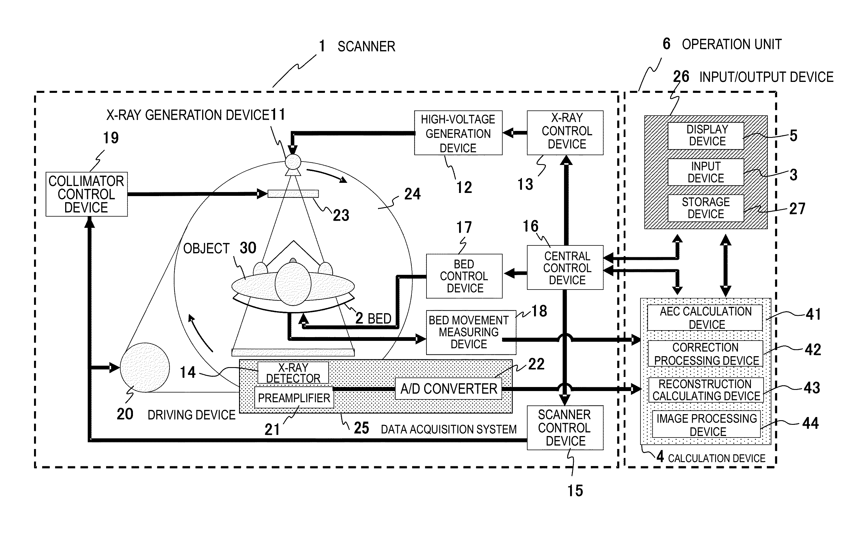
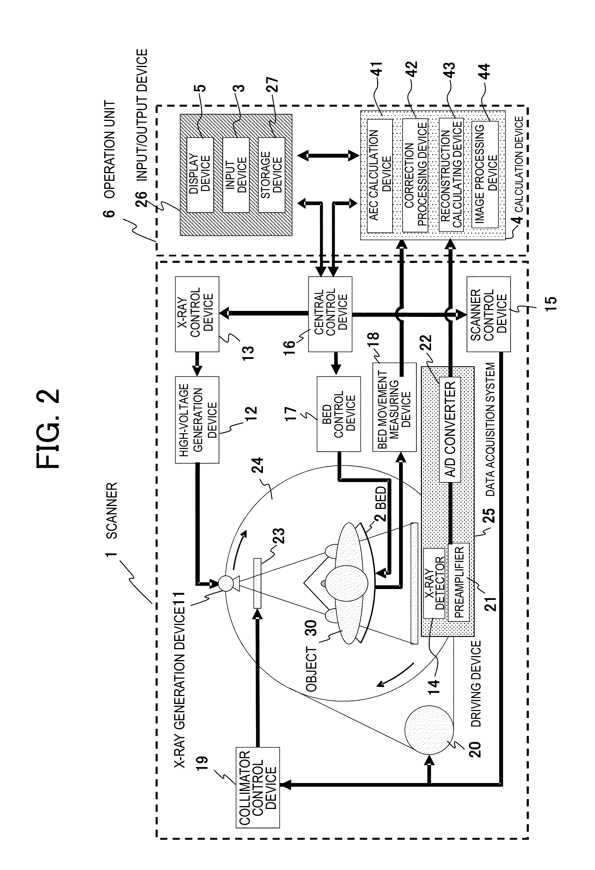
[0040]The correction processing device 42 performs, on an output signal from the data acquisition system 25, a process of maintaining a local mean value of output signals of a plurality of predetermined detection elements centering on a focused detection element and of reducing a variance corresponding to a system noise amount included in the output signals of the plurality of predetermined detection elements.

[0041]FIG. 3 is a block diagram illustrating a specific configuration of the correction processing device 42, and FIG. 4 is a flowchart illustrating an operation of the correction processing device 42. As illustrated in FIG. 3, the correction processing device 42 is configured to include a preprocessor 131, a noise reduction processor 132, a positive number converter 133, a correction processor 134, an evaluation function parameter setter 136, and a threshold value setter 135. The above-described constituent elements may be constituted of hardware obtained through combination o...

embodiment 2

[0088]In Embodiment 2, the correction processing device 42 performs a process for achieving a desired noise reduction effect more accurately even in a case where an average of measurement data of detection elements j around a focused detection element i is considerably small.

[0089]A configuration of the correction processing device 42 of Embodiment 2 is the same as in FIG. 3 of Embodiment 1, and a flow of a process performed by the correction processing device 42 is the same as illustrated in FIG. 4. However, in Embodiment 2, Equation (9) is used instead of Equation (1) in step 402 of FIG. 4. Equation (9) relates to a PWLS function Q(s).

[Equation9]Q(s)=∑i=1If(Ti)(di-si)2+∑i=1Iαi∑j∈Niwij(si-sj)2(9)

[0090]In Equation (9), symbols common to Equation (1) indicate the same parameters as in Embodiment 1. In Equation (9), αi, which is a penalty coefficient, is not equivalent for all data and is defined for each detection element i, and αi is set to become greater as measurement data di has ...

embodiment 3

[0093]In a case where an X-ray absorption coefficient of an object does not depend on energy of X-rays, a relationship between an average value and a variance of data can be represented as a straight line as in the comparative example 1 in FIG. 8. In contrast, in a case where the X-ray absorption coefficient considerably depends on the energy, a relationship between both of the two is not represented as a straight line (called a beam hardening effect). Therefore, in Embodiment 3, the correction processing device 42 performs a process for realizing a desired noise reduction effect more accurately by taking into consideration an influence of the beam hardening effect of X-rays detected by the X-ray detector 14.

[0094]A configuration of the correction processing device 42 of Embodiment 3 is the same as in FIG. 3 of Embodiment 1, and a flow of a process performed by the correction processing device 42 is the same as illustrated in FIG. 4. However, in Embodiment 3, Equation (11) is used i...


PUM


Abstract

In order to provide a technique for reducing system noise from an output signal value (measurement data), an X-ray CT apparatus includes an X-ray generation unit that irradiates X-rays to an object, an X-ray detector that detects the X-rays transmitted through the object, a correction processing unit that corrects an output signal from the X-ray detector, and a reconstruction calculating unit that reconstructs an image on the basis of an output from the correction processing unit, in which the X-ray detector includes arranged detection elements, and in which the correction processing unit maintains an average value of output signal values of a plurality of predetermined detection elements centering on a focused detection element among the detection elements, and also reduces a variance of the output signal values of the plurality of predetermined detection elements centering on the focused detection element.

Description

TECHNICAL FIELD[0001]The present invention relates to an X-ray CT apparatus, and particularly to a noise reduction technique which is suitable for an apparatus having an automatic exposure control function of adjusting an X-ray irradiation dose during scanning.BACKGROUND ART[0002]An X-ray CT apparatus irradiates X-rays from the vicinity of an object, and generates a distribution of an X-ray absorption coefficient of the object as an image on the basis of projection data acquired at a plurality of projection angles. As an X-ray irradiation dose becomes larger, an image with less noise can be acquired, and thus image quality is improved. On the other hand, in recent years, an influence of exposure to X-rays on the human body has become problematic, and thus techniques have been actively examined in which image quality for a doctor to perform diagnosis is obtained even in a case where an X-ray irradiation dose is minimized. As one of the techniques, an automatic exposure control (AEC) ...

Claims


Application Information

Patent Timeline
Patent Type & Authority Applications(United States)
IPC IPC(8): A61B6/00A61B6/03
CPCA61B6/5258A61B6/542A61B6/032A61B6/5205A61B6/544
Inventor TAKAHASHI, HISASHIGOTO, TAIGAHIROKAWA, KOICHI
Owner FUJIFILM HEALTHCARE CORP
Why Eureka
Try Eureka