Hearing aid device with an output amplifier having a sigma-delta modulator
Inactive Publication Date: 2006-08-31
SIVANTOS PTE LTD
14 Cites 6 Cited by
AI-Extracted Technical Summary
Problems solved by technology
Due to the high system clock frequency of a sigma-delta modulator, its energy consumption is, however, quite high, which is disadvantageou...
Benefits of technology
[0009] An object of the present invention is to provide a hearing aid device with an output amplifier that has a sig...
Abstract
In a digital hearing aid device with an output amplifier having a sigma-delta modulator, the output transducer has a high current consumption even when no output signal perceivable as an acoustic output signal is generated. A linear digital filtering in connection with the sigma-delta modulation reduces the number of the high-frequency edges in the (typically) pulse-density-modulated output signal.
Application Domain
Electric signal transmission systemsHearing device energy consumption reduction +4
Technology Topic
Pulse-density modulationDigital hearing aid +9
Image
Examples
- Experimental program(1)
Example
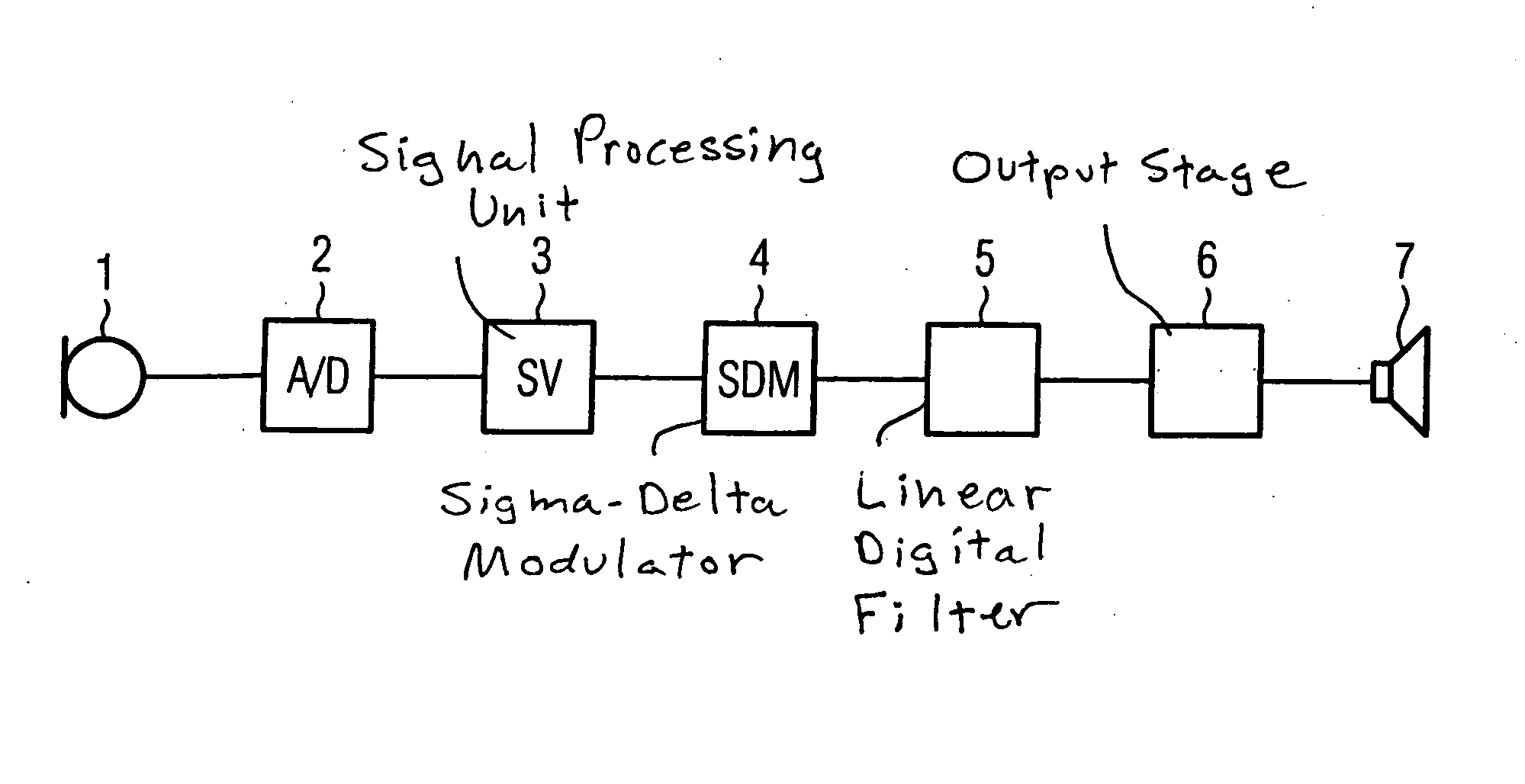
[0018]FIG. 1 shows the signal path of a hearing aid device between an input transducer and an output transducer. An input signal is acquired by the input transducer and converted into an electrical signal. At least one microphone 1 that acquires an acoustic input signal typically serves as the input transducer. Modern hearing aid devices frequently have a microphone system with a number of microphones in order to achieve a reception dependent on the incident direction of acoustic signals (a directional characteristic). The input transducer alternatively can be fashioned as a telephone coil or an antenna for acquisition of electromagnetic input signals. In a digital hearing aid device, the input signals converted into electrical input signals by the input transducer (the microphone 1 in the exemplary embodiment) are initially converted into a digital signal by an A/D converter 2, and this digital signal is supplied to a signal processing unit 3 for further processing and amplification. The further processing and amplification normally ensues dependent on the signal frequency, to compensate the individual hearing loss of a hearing aid device user. The signal filterings typical in hearing aid devices thus occur in the signal processing unit 3. In digital hearing aid devices, the conversion of the digital output signal of the signal processing unit 3 into a signal that can be supplied to the output transducer typically ensues via a sigma-delta modulator 4 that normally emits a pulse-density-modulated signal. In a digital hearing aid device, the output signal is conventionally initially supplied to an output stage 6 and from this directly to an output transducer fashioned as an earpiece 7. Low-pass filtering of the output signal supplied to the earpiece 7 is normally not required since the earpiece 7 already exhibits a strong low-pass characteristic anyway. Nevertheless, it is possible that an analog low-pass filter for suppression of high-frequency signal portions is connected upstream from an output transducer 7, in particular when an earpiece (typically used) is not used as an output transducer. Namely, other types of output transducers in hearing aid devices are known, for example for generation of mechanical oscillations that directly excite specific parts of the ear (such as, for example, the ossicles) to oscillations or that directly stimulate nerve cells of the ear. Normally, however, digital filter means have not been used between the sigma-delta modulator 4 and the output stage 6 so far. In contrast to a, linear digital filter is provided in this segment of the signal path of the hearing aid device according to the invention. This serves to reduce the number of high-frequency edges in the typically pulse-density-modulated output signal of the sigma-delta modulator 4.
[0019] The input signal in the filter 5 is a single bit stream. A higher-order encoding of the output signals can be used as an output signal over both earpiece feed lines. In particular three different states, for example “1,0” (1st state), “0,0” (2nd state), “0,1” (3rd state), are realized by two output signal lines of the filter 5.
[0020]FIG. 2 shows a first and very simple embodiment of the linear digital filter 5 that is designated as a filter unit 51. At its input, the filter unit 51 receives a 1-bit data stream that is directly supplied to the first input of an adder 512 as well as to the second input of the adder 512 after a delay produced by a delay element 511. In the simplest case, a signal delay by one clock pulse ensues in the delay element 511, but a delay of a higher number of clock pulses (generally by “n” clock pulses) can also ensue.
[0021] The output signal of the filter unit 51 can have the numerical values 0, 1 or 2. It is accordingly a 2-bit signal. The output stage 6 for impedance conversion can thereby be selected such that, upon application of a “2” (thus the voltage states “1, 0” at both output signal lines), coil current flows through the exciter coil of the earpiece 7 in one direction, upon application of a “1” (thus the voltage states “0, 1” at both output signal lines) coil current flows through the exciter coil in the opposite direction, and upon application of a “0” (thus the voltage states “0, 0” at both output signal lines) the exciter coil is not excited. Given this approach, the low-current effect caused by the filter can also be easily illustrated. Namely, if no signal is present at the input transducer (for example at the microphone 1 according to FIG. 1), the sigma-delta modulator 4 supplies an output signal with a 1-bit output which changes between 0 and 1 with the clock frequency with which the sigma-delta modulator 4 is operated. This in turn causes a high current consumption of the earpiece 7, although its membrane experiences nearly no deflection in this state. It is different in the invention, where in this state a “0” is always present at the input of the output stage 6 and the coil of the earpiece 7 is thereby not excited. Thus no current consumption by the earpiece 7 occurs.
[0022] It is noted that the three logical count values “0”, “1”, “2” only represent three different output states of the linear digital filter 5. Naturally, these could be designated otherwise, for example 0, 0.5, 1 or −1, 0, +1. These three output states are converted in the output stage 6 such that the positive input voltage of the earpiece 7, the negative input voltage of the earpiece 7 or no voltage is applied via the exciter coil of the earpiece 7.
[0023] In a further embodiment of the invention, the filter is a filter unit 52A with a delay element 521 and a change-over switch 522. An input bit stream in the filter unit 52A is directly supplied to a first input of the change-over switch 522 and, on the other hand, supplied to a second input of the change-over switch 522 through a delay element 521. The delay in the delay element 521 generally ensues by “m” clock pulses, whereby m is a natural number. The change-over switch 522 switches between both inputs with the clock frequency T, whereby T is a multiple of the clock frequency with which the sigma-delta modulator is operated. The filter unit 52A serves for conversion of an input bit stream into an output bit stream, in that a specific frequency is suppressed dependent on the delay due to the delay element 521. A notch filter is accordingly realized by the filter unit 42A. It can be shown that the filter 52A, like the filter 51, is a linear filter.
[0024] Given the use of the filter 52A in the signal path of a hearing aid device according to FIG. 1, two similar filters 52A and 52B are advantageously connected in parallel, whereby a filter unit 52 results. The filter unit 52 thereby converts a two-bit input signal into a two-bit output signal. The filter unit 52 can thus be directly connected to a filter 51 according to FIG. 2. Moreover, it is possible to connect a number of filters 52 directly in series, one after the other. By the selection of different signal delays, a number of notches (in particular a number of closely adjoining notches) can then be generated. It is thus possible to suppress frequency ranges in the output signal.
[0025]FIG. 4 shows a further embodiment of a digital filter according to the invention. The filter unit 53A has a change-over switch 51, a delay element 532 and an adder 533. An input bit stream into the filter unit 53A is supplied to the output of the change-over switch 531. The first output of the change-over switch 531 is directly supplied to the second input of the adder 533 with the first input of the adder 533 and the second output of the change-over switch 531 through the delay element 532. This filter unit 53A also converts an input bit stream into an output bit stream and, dependent on the signal delay in the delay element 532, generates a notch at a specific signal frequency.
[0026] Just as in the filter 52 according to FIG. 3, here two similar filters 53A and 53B complement one another to form a filter 53, since it converts a two-bit input stream into a two-bit output stream. The filter 53 can also be directly connected to a filter 51 according to FIG. 2 and, if applicable, multiple filters 53 can be connected in series.
[0027] The exemplary embodiment according to FIG. 5 shows a section of the signal path of a hearing aid device between a sigma-delta modulator 4 and an output stage 6 between which filter means 51 and 52 according to FIGS. 2 and 3 are present. A one-bit output signal of the sigma-delta modulator 4 forms the input signal in the filter unit 51. The two-bit output signal arising from this serves as an input signal to a first filter unit 52. A further filter unit 52 is in turn connected downstream from this. Its output signal is in turn supplied to the output stage 6. The first filter unit 52 is clocked at twice the clock frequency of the sigma-delta modulator, and the second filter unit 52 is clocked at four times the clock frequency of the sigma-delta modulator. In the exemplary embodiment, this is achieved by the clock pulse generated by an oscillator 8 being halved in each of dividers 9 and 10.
[0028] By means of the filter units 51 and 52, multiple notches are generated that serve for suppression of interference signals that, for example, are caused by the sigma-delta modulator 4. The filter in particular serves for reduction of electromagnetic interference radiation that is emitted via the earpiece coil. Furthermore, the reduction of the number of high-frequency edges in the typical pulse-density-modulated output signal of the filter units 51 and 52 leads to a reduced current consumption of the output transducer.
[0029] Although modifications and changes may be suggested by those skilled in the art, it is the intention of the inventors to embody within the patent warranted hereon all changes and modifications as reasonably and properly come within the scope of their contribution to the art.
PUM


Description & Claims & Application Information
We can also present the details of the Description, Claims and Application information to help users get a comprehensive understanding of the technical details of the patent, such as background art, summary of invention, brief description of drawings, description of embodiments, and other original content. On the other hand, users can also determine the specific scope of protection of the technology through the list of claims; as well as understand the changes in the life cycle of the technology with the presentation of the patent timeline. Login to view more.