Method and apparatus for noise control in ultrasonic sensors

a technology of ultrasonic sensors and noise control, applied in the field of electric controls, can solve the problems of unintentional change of control load state, waste of control load energy, and lowering so as to reduce environmental noise-induced false triggering, reduce receiver sensitivity to inappropriate activation, and reduce the effect of total ultrasonic energy

Active Publication Date: 2016-08-16
THE WATT STOPPER
View PDF17 Cites 7 Cited by
  • Summary
  • Abstract
  • Description
  • Claims
  • Application Information

AI Technical Summary

Benefits of technology

[0005]The adjustable voltage regulator under control of a microcontroller applies controlled amplitude voltage in the range of 5 to 9 VDC to the sensor transmitter to adjust the output amplitude of the transmitter. The adjustable amplitude transmitter allows an occupancy sensor to have its total output energy adjusted to reduce environmental noise-induced false triggering and to conform to the area to be covered. Lowering the total ultrasonic energy in the monitored space lowers the sensitivity of the receiver to inappropriate activations. Lowering the input power to the transmitter also lowers the total internal system noise and provides an improved signal to noise ratio in the receiver.

Problems solved by technology

This type of environmental noise may cause a false trigger, as is known in the art, causing the controlled load to change state unintentionally.
Typically, the false trigger noise is interpreted as occupancy, causing the controlled load to turn on and waste energy when there is no one in the monitored space.
Lowering the total ultrasonic energy in the monitored space lowers the sensitivity of the receiver to inappropriate activations.

Method used


Image

  • Method and apparatus for noise control in ultrasonic sensors
  • Method and apparatus for noise control in ultrasonic sensors
  • Method and apparatus for noise control in ultrasonic sensors

Examples


Embodiment Construction

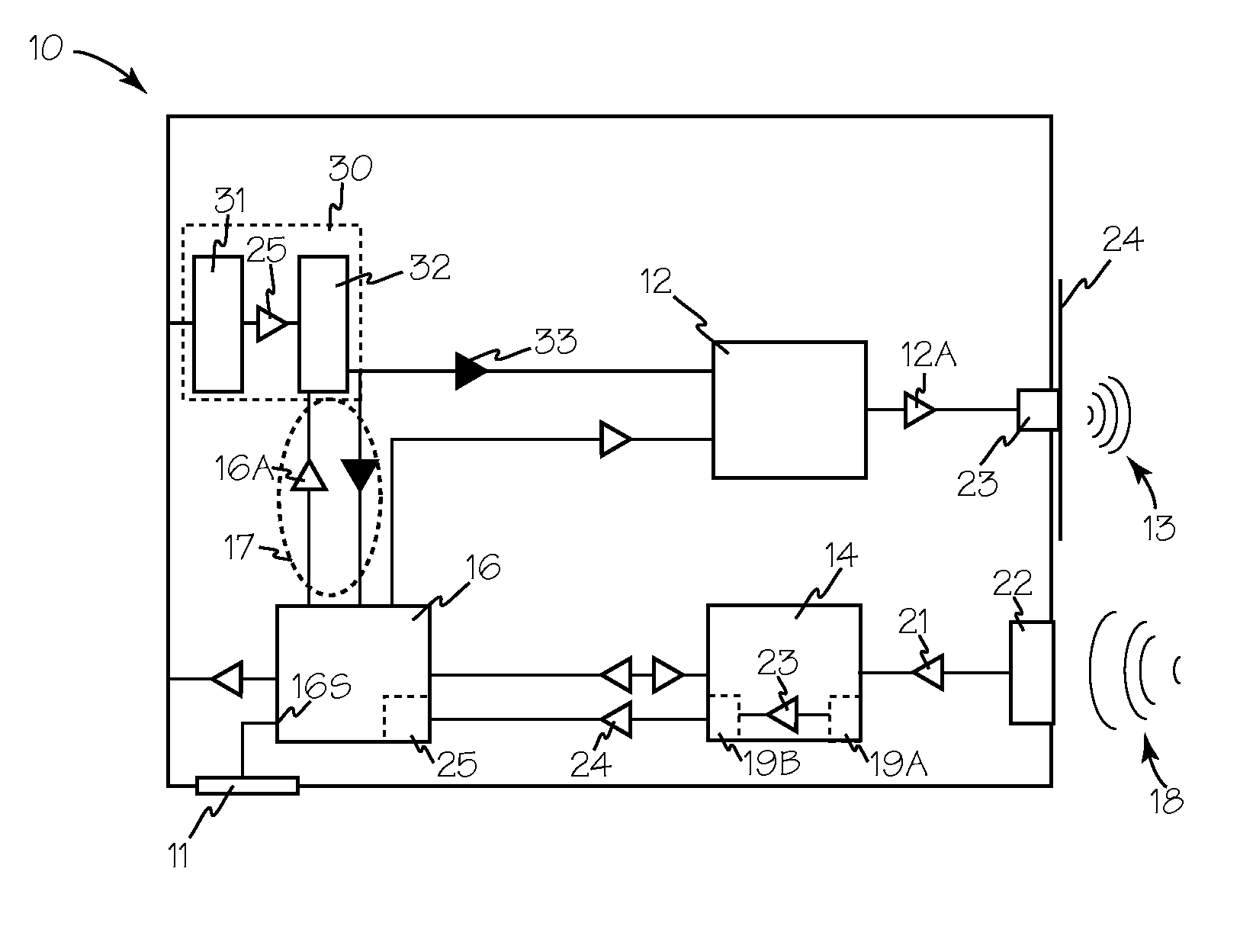
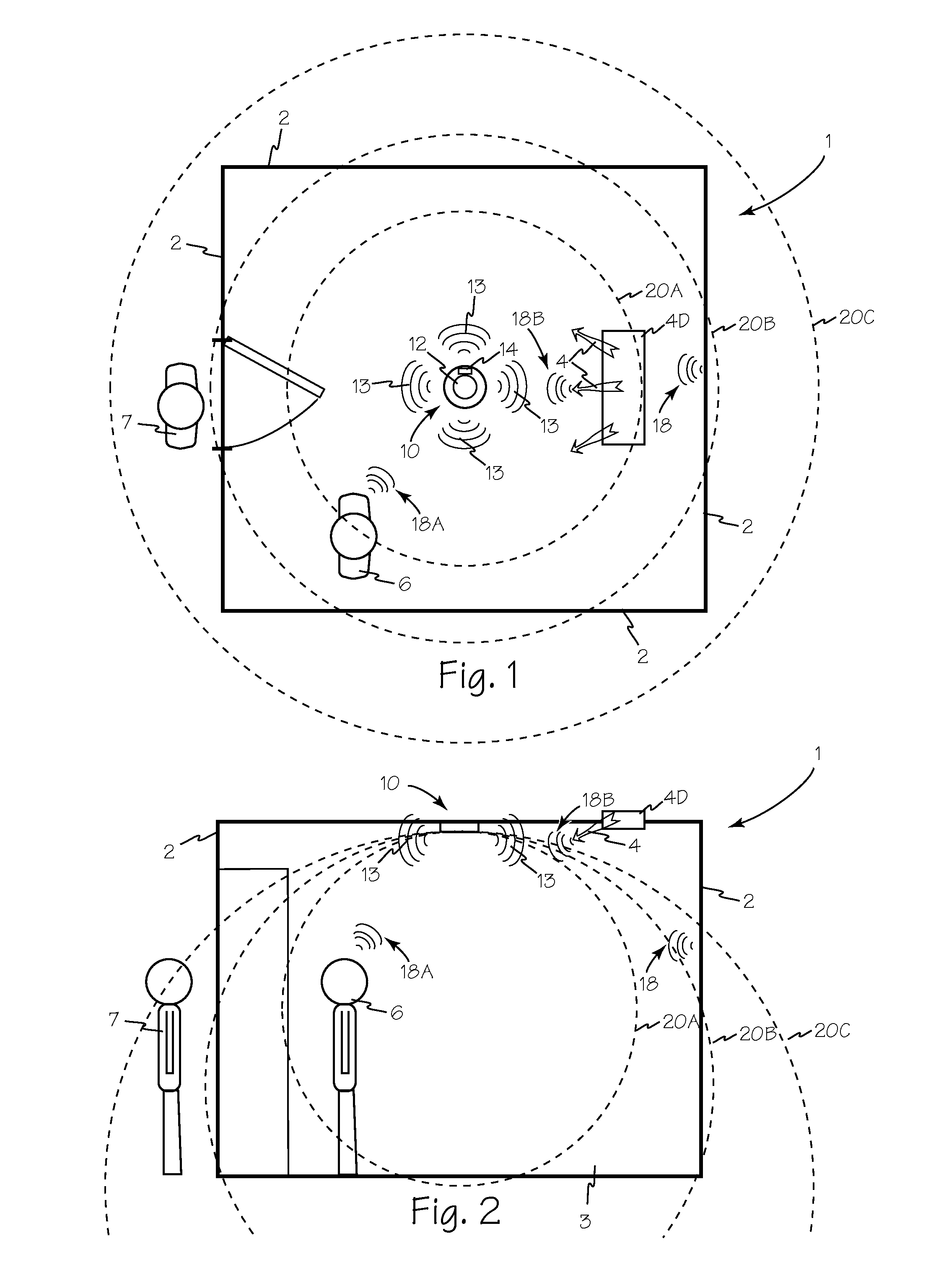
[0013]FIG. 1 is a top view, and FIG. 2 is a side view of room 1 equipped with adjustable amplitude active ultrasonic occupancy sensor 10 which is illustrated in FIG. 5. Sensor 10 includes a transmitter 12 and a receiver 14 which receives energy from power supply 30. Operation of transmitter 12, receiver 14 and power supply 30 are all controlled by microprocessor or controller 16. Transmitter 12 continuously transmits ultrasonic energy 13 into room 1. Ultrasonic energy 13 is reflected as incoming energy 18 by anything occupying room 1 including walls 2 floor 3 and as environmental signal 18B when reflected by transient environmental elements such as HVAC air 4. The amplitude of power applied to transmitter 12 can be adjusted to control the amplitude of ultrasonic output signal 13 and thus, the amplitude of reflected signals from the contents of the room, such as reflected signals 18, or the environmental elements of the room such as reflected signal 18B. The amplitude of output energ...


PUM

PropertyMeasurementUnit
response timeaaaaaaaaaa

Abstract

The adjustable voltage regulator under control of a microcontroller applies controlled amplitude voltage in the range of 5 to 9 VDC to the sensor transmitter to adjust the output amplitude of the transmitter. The adjustable amplitude transmitter allows an occupancy sensor to have its total output energy adjusted to reduce environmental noise-induced false triggering and to conform to the area to be covered. Lowering the total ultrasonic energy in the monitored space lowers the sensitivity of the receiver to inappropriate activations. Lowering the input power to the transmitter also lowers the total internal system noise and provides an improved signal to noise ratio in the receiver.

Description

RELATED APPLICATIONS[0001]This application claims priority to copending U.S. Provisional Patent application 61 / 794,694 filed Mar. 15, 2013.FIELD OF THE INVENTIONS[0002]The inventions described below relate to the field of electrical controls and more specifically, sensors for automatically controlling electrical loads such as lighting.BACKGROUND OF THE INVENTIONS[0003]Active ultrasonic room occupancy sensors are equipped with an ultrasonic transmitter having an output with a generally fixed amplitude. Ultrasonic occupancy sensors are sensitive to environmental noise such as forced air, e.g, from a HVAC vent, and other extraneous air pressure changes that may be interpreted by the ultrasonic receiver as a return ultrasonic signal representing an occupancy state. This type of environmental noise may cause a false trigger, as is known in the art, causing the controlled load to change state unintentionally. Typically, the false trigger noise is interpreted as occupancy, causing the cont...

Claims


Application Information

Patent Timeline
Patent Type & Authority Patents(United States)
IPC IPC(8): G01N29/00G01S7/52G01N29/34G01V1/24G01S15/04H05B37/02G01V1/38
CPCG01V1/247G01S7/52004G01N29/34G01S15/04H05B37/0227G01V1/3852H05B47/115H05B47/105G01V1/001
Inventor WEIDMAN, LOUIACHEN, AIZHONGFAN, CHENGHAO
Owner THE WATT STOPPER
Why Eureka
Try Eureka