Color image forming method and apparatus, and microcapsule toner for use therewith

a technology of microcapsules and forming methods, which is applied in the direction of electrographic processes, instruments, and thermography, can solve the problems of complex management of consumption articles, increase in the number of components of the apparatus, and large size of the apparatus, and achieve the effect of reducing the energy of the ultrasonic outpu

Active Publication Date: 2004-04-22
CASIO COMPUTER CO LTD
View PDF6 Cites 6 Cited by
  • Summary
  • Abstract
  • Description
  • Claims
  • Application Information

AI Technical Summary

Benefits of technology

0070] By such composition, a bandwidth of resonant frequencies of ultrasonic waves required for the respective smaller microcapsules of four different colors is reduced as a whole to thereby reduce the energy of the ultrasonic output greatly.

Problems solved by technology

Thus, management of the consumption articles is complicated.
Thus, the number of components of the apparatus increases and the apparatus itself becomes large-sized.
Thus, assembling the apparatus in a factory requires much time, which would lead to a reduction in the work efficiency.
The structure also becomes complicated and is disadvantageous in view of reducing the apparatus weight.
In the U.S. Pat. No. 4,734,704 and Published Unexamined Patent Application Hei 11-58832 use dedicated recording paper coated with an ink layer containing microcapsules, the whole surface of the recording paper is basically coated with ink, which increases the cost.
In addition, general paper cannot be used in this patent.
Further more, since a plurality of color printing steps is repeated, so that a discrepancy in position between color image is difficult to correct and complication of the composition of the apparatus cannot be avoided.
Thus, the transparency of light to coloring matter capsules contained in the toner is low.
Therefore, this method cannot satisfy recent high-speed printing.
However, the four kinds of coloring hollow grains are dispersed in the receiving section, so that management of a quantity of each of the four kinds of coloring hollow grains when the quantity changes is complicated.

Method used


Image

  • Color image forming method and apparatus, and microcapsule toner for use therewith
  • Color image forming method and apparatus, and microcapsule toner for use therewith
  • Color image forming method and apparatus, and microcapsule toner for use therewith

Examples


first embodiment

[0122] First Embodiment

[0123] First, a whole composition of the invention will be described as a first embodiment.

[0124] FIG. 1 illustrates a whole composition of a color image forming apparatus of the first embodiment. The color image forming apparatus is a printer connected to a personal computer as a host device or otherwise to a LAN (Local Area Network), for example, on a peer-to-peer basis.

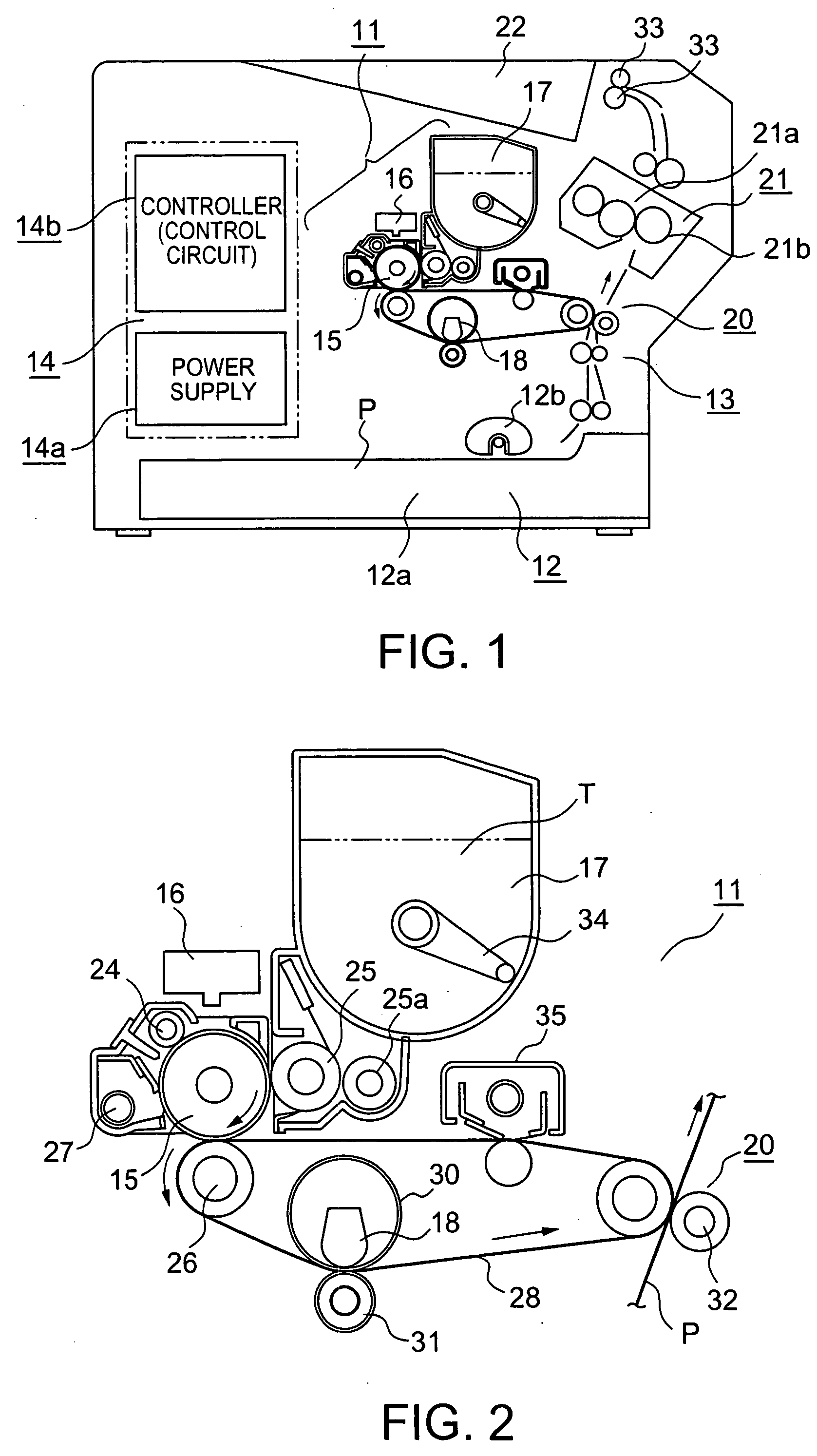
[0125] The color image forming apparatus of FIG. 1 includes an image forming section 11, a paper feeder 12, a paper conveyer 13, and a power supply / control unit 14. The image forming unit 11 includes a photosensitive drum 15, an optical write head 16, a capsule toner hopper 17, and an ultrasonic line head 18.

[0126] The paper feeder 12 includes a paper cassette 12a and a paper feed roller 12b. Recording paper P contained in the paper cassette 12a is fed out from the paper cassette 12a in accordance with rotation (a single rotation) of the paper feed roller 12b and then conveyed to the paper co...

second embodiment

[0214] Second Embodiment

[0215] This embodiment discloses the use of the liquid developing system. As shown in FIG. 20, in this system a developing roll 120 that feeds capsule toners T containing the smaller microcapsules 41M, 41C, 41Y, and 41K and a developer including a carrier liquid CL; and a squeeze roller 121 that collects an unnecessary carrier liquid CL adhering to the photosensitive drum 15 are provided on the outer periphery of the photosensitive drum 15. FIG. 21 shows the developing roll 120, the squeeze roller 121 and their vicinities in an enlarged view.

[0216] The developer is fed to the developing roll 120. The developer on the developing roll 120 is in contact with the photosensitive drum 15 to thereby cause the capsule toners T in the developer to statically adhere to a static latent image on the drum. In this developing process, a part of the carrier liquid CL on the developing roll 120 moves onto the photosensitive drum 15. The capsule toners T and an excess carrier...

third embodiment

[0219] Third Embodiment

[0220] FIGS. 22 and 23 illustrate further compositions of the liquid developing system which are different from the second embodiment in that the ultrasonic line head 18 is disposed between the develop roll 120 and the squeeze roller 121. In this case, the ultrasonic line head 18 is in contact with the capsule toners T and the carrier liquid CL.

[0221] Therefore, in such arrangement the ultrasonic line head 18 is in contact with the carrier liquid CL on the photosensitive drum 15. Therefore, the ultrasonic waves are transmitted efficiently to the capsule toners T without being transmitted through air to thereby provide a clearer printed image.


PUM

PropertyMeasurementUnit
diameteraaaaaaaaaa
diametersaaaaaaaaaa
voltageaaaaaaaaaa

Abstract

A color image forming method and apparatus using larger microcapsules each of which contains a plurality of kinds of smaller microcapsules scattered within the larger microcapsule, reacting substances that are mixed with each other to perform a coloring reaction being scattered inside and outside the smaller microcapsule. A protective wall of each smaller microcapsule is broken with a corresponding predetermined ultrasonic stimulus depending upon color component information to thereby cause the reacting substances to diffuse with each other to perform a coloring reaction and hence image printing. The conditions for breaking the protective walls of the respective smaller microcapsules that contain a color former component vary from smaller microcapsule to smaller microcapsule, or are determined depending upon the outer shapes, materials and thickness of the protective walls of the smaller microcapsules.

Description

[0001] 1. Field of the Invention[0002] The present invention relates to a color image forming method and apparatus using new microcapsule toner breakable with external stimulus.[0003] 2. Description of the Related Art[0004] When it comes to color prints, silver (salt) photographs are cited since this technique has been the mainstream for a long time. However, as computers have spread as information devices including personal computers as their core, printers as the peripheral devices of the computers also have spread. As the printers, various color printers have been proposed. Especially, printers of electrophotographic, thermal transfer, inkjet types have made remarkable progress. Color images created by those printers match silver salt photographs taken by analog cameras used in the past in terms of beautifulness and resolution, so that the printers tends to supersede the analog cameras.[0005] FIG. 49 illustrates a prior-art so-called tandem type color image forming apparatus of a...

Claims


Application Information

Patent Timeline
Patent Type & Authority Applications(United States)
IPC IPC(8): B41M5/28B41M5/382B41M5/398G03G9/093G03G15/01
CPCB41M5/287B41M5/38271B41M5/398G03G15/0121G03G9/0935G03G9/09392G03G9/093
Inventor KAWADA, KAZUMASASHIMIZU, SHIGERUEBISAWA, ISAOYAMASAKI, SHUICHIMATSUOKA, YOSHIYUKIYOSHIDA, NAOTOKAMEI, KOICHIONO, NORIKINAKAHARA, MASAFUMIASAKO, KENICHIROKOBAYASHI, KENJISUGAMA, KOSUKE
Owner CASIO COMPUTER CO LTD
Why Eureka
Try Eureka