Ultrasonic sensor control system for occupancy sensing

a sensor control and ultrasonic technology, applied in the field of electric control, can solve the problems of ineffective sensitivity of the receiver in minimizing inappropriate activation, too large coverage area of the sensor, and inability to detect the presence of objects, etc., and achieve the effect of reducing noise in the system, improving receiver efficiency, and high efficiency

Active Publication Date: 2014-09-30
THE WATT STOPPER
View PDF14 Cites 4 Cited by
  • Summary
  • Abstract
  • Description
  • Claims
  • Application Information

AI Technical Summary

Benefits of technology

[0004]The devices and methods described below provide for an active ultrasonic room occupancy sensor with the output amplitude of the transmitter controlled by the amplitude of power applied to the transmitter to control the zone of coverage for a sensor. An adjustable voltage regulator under control of a microcontroller applies controlled amplitude voltage in the range of 5 to 9 VDC to the transmitter to adjust the output amplitude of the transmitter. The adjustable amplitude transmitter allows an occupancy sensor to have its total output energy adjusted to conform to the area to be covered. Lowering the total ultrasonic energy in the monitored space lowers the sensitivity of the receiver to inappropriate activations. Lowering the input power to the transmitter also lowers the total internal system noise and provides an improved signal to noise ratio in the receiver.
[0005]An active ultrasonic room occupancy sensor may also control of the amplitude of power applied to the receiver to control the sensitivity of the receiver. An adjustable voltage regulator under control of a microcontroller applies controlled amplitude voltage in the range of 5 to 9 VDC to the receiver to adjust the output amplitude of the receiver. Lowering the level of power applied to the input of an ultrasonic receiver also lowers the input noise level to the receiver. In multistage receiver systems the power is controlled to the first stage where the input signal is relatively small and the signal to noise ratio is relatively high. Improving the performance of the first stage provides correspondingly larger benefits in subsequent stages where both the system noise and the sensor signal are both amplified.
[0007]An active ultrasonic room occupancy sensor with an improved power system includes an intermediate power regulator between the 24 VDC power supply and the adjustable voltage regulator. The fixed regulator steps down the applied power from 24 VDC to about 12 VDC and the adjustable regulator reduces the power to 5 to 9 VDC as discussed above. The fixed regulator is a high efficiency switching regulator that performs two functions. First, it lower the noise from the main 24 VDC power supply and lower noise in the system improves the receiver efficiency. Second, the fixed regulator reduces total power consumption and wasted heat since each regulator is only regulating down a few volts from the input power applied. Use of a high efficiency fixed regulator to apply power to the adjustable regulator also eliminates the need for a feedback loop to monitor the output of the power supply.

Problems solved by technology

This configuration often resulted in sensors with too large a coverage area being selected for a given area.
With fixed energy transmitters, distant targets reflect significant energy leading to inappropriate activations.
The sensitivity of the receiver is often ineffective in minimizing inappropriate activations.
Lowering the total ultrasonic energy in the monitored space lowers the sensitivity of the receiver to inappropriate activations.
Second, the fixed regulator reduces total power consumption and wasted heat since each regulator is only regulating down a few volts from the input power applied.

Method used


Image

  • Ultrasonic sensor control system for occupancy sensing
  • Ultrasonic sensor control system for occupancy sensing
  • Ultrasonic sensor control system for occupancy sensing

Examples


Embodiment Construction

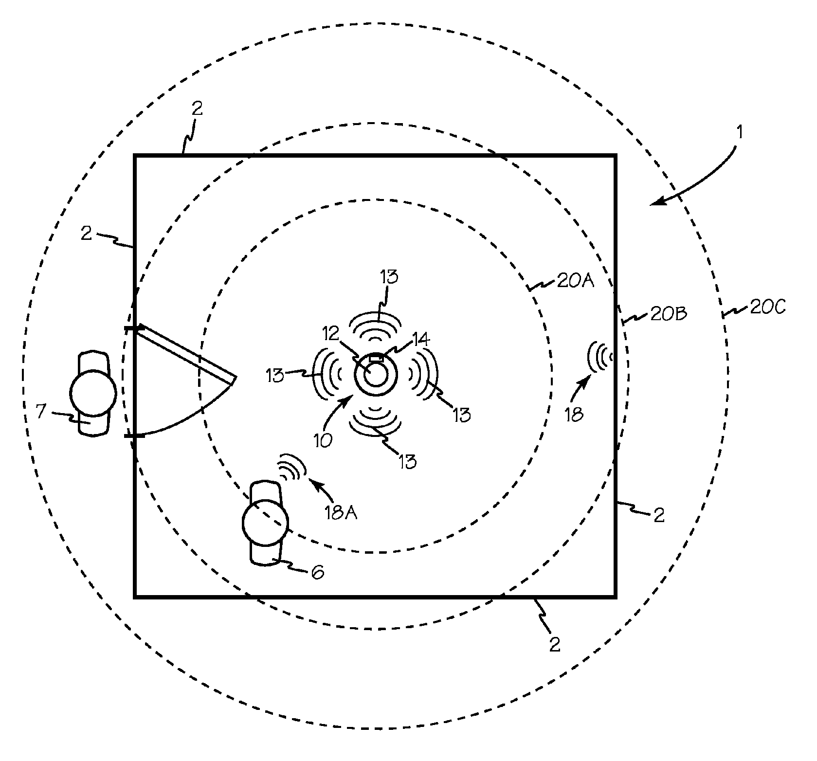
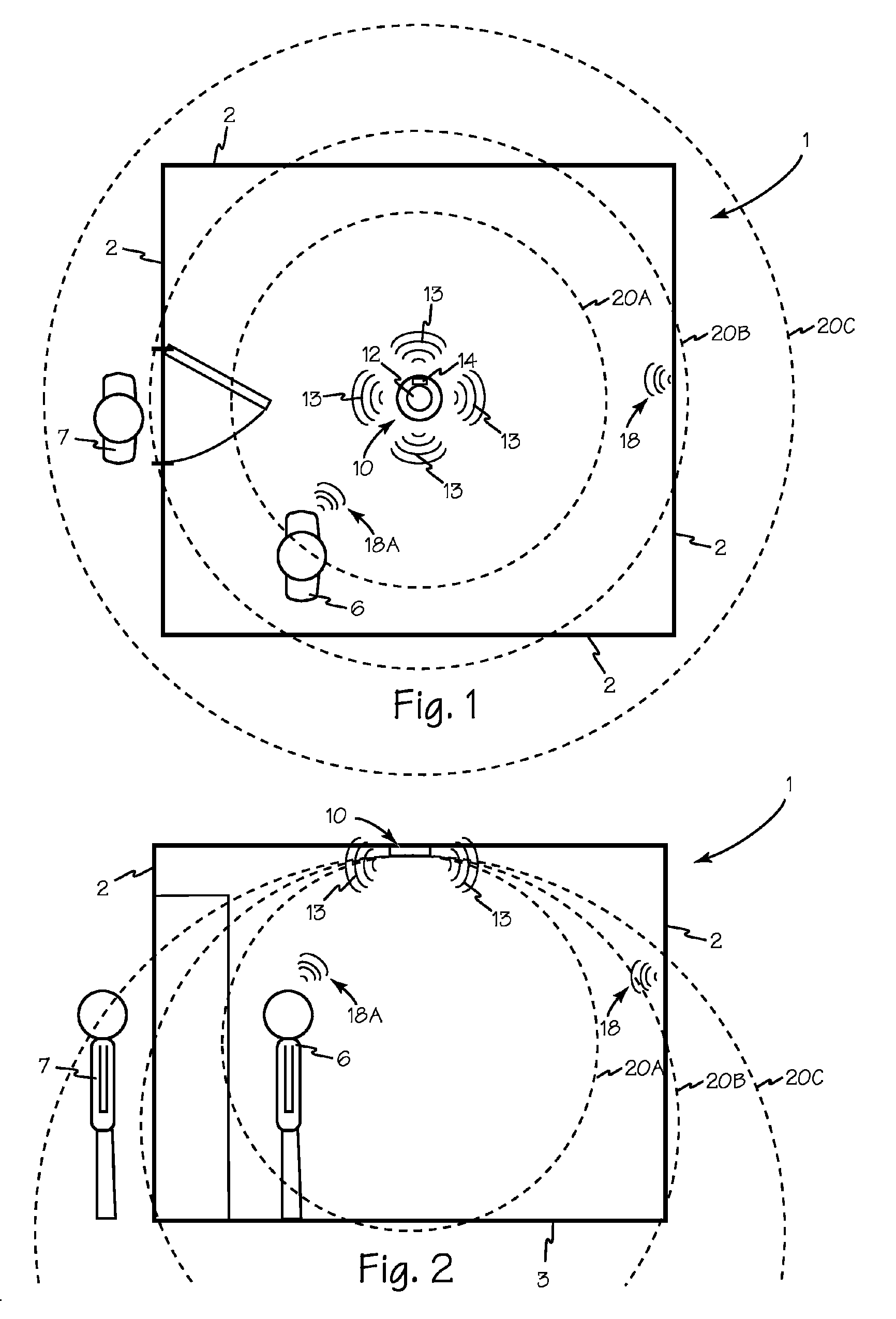
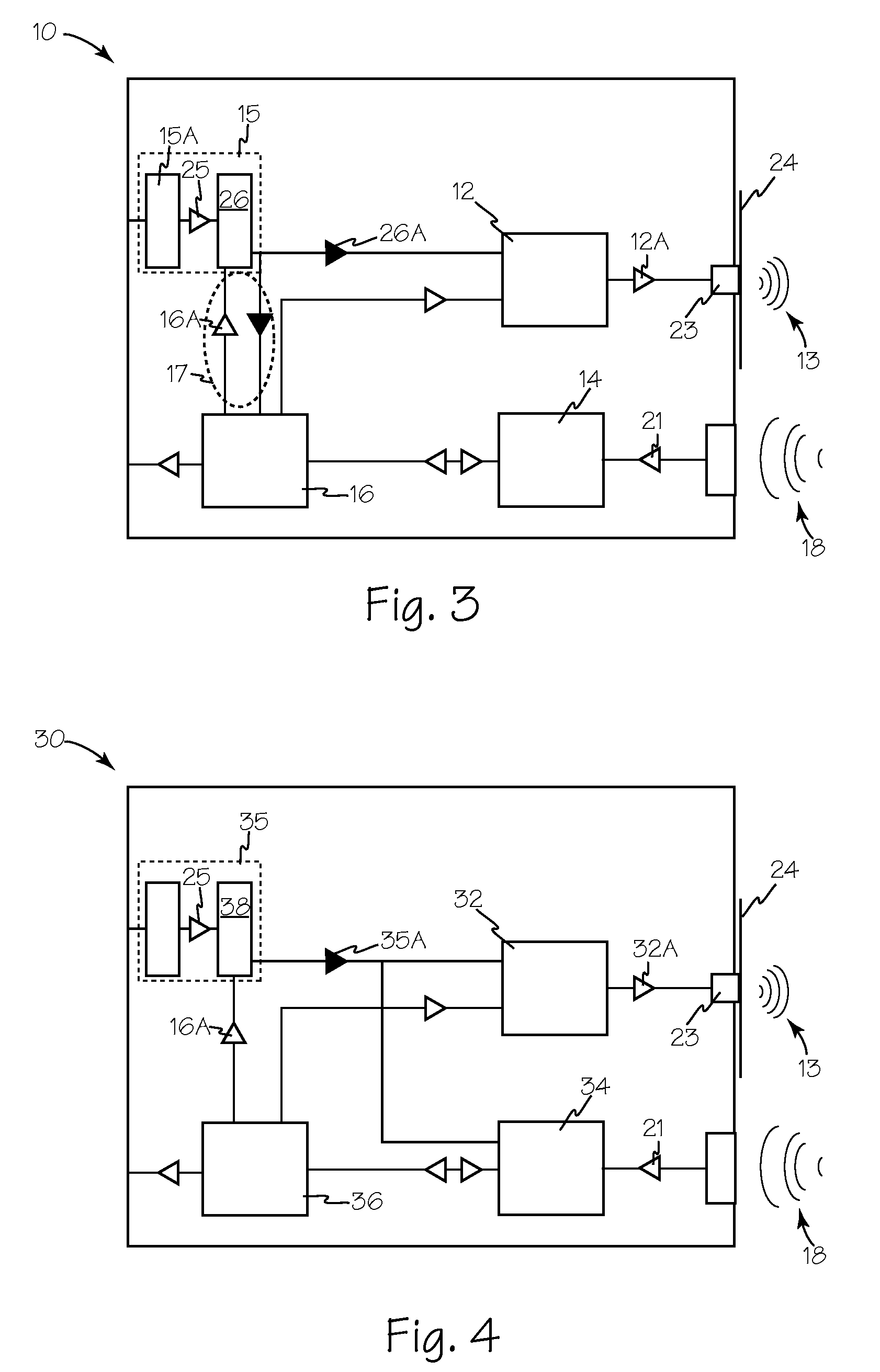
[0014]FIG. 1 is a top view, and FIG. 2 is a side view of room 1 equipped with adjustable amplitude active ultrasonic occupancy sensor 10 which is illustrated in FIG. 3. Sensor 10 includes a transmitter 12 and a receiver 14 which receives energy from power supply 15. Operation of transmitter 12, receiver 14 and power supply 15 are all controlled by microprocessor or controller 16. Transmitter 12 continuously transmits ultrasonic energy 13 into room 1. Ultrasonic energy 13 is reflected as incoming energy 18 by anything occupying room 1 including walls 2 and floor 3. The amplitude of power applied to transmitter 12 can be adjusted to control the amplitude of ultrasonic output signal 13 and thus, the amplitude of reflected signals from the contents of the room, such as reflected signal 18. The amplitude of output energy 16 is set such that reflected signals 18 from the edges of a desired zone of sensitivity such as zones 20A, 20B and 20C are at or below the noise threshold of receiver 1...


PUM

PropertyMeasurementUnit
poweraaaaaaaaaa
voltageaaaaaaaaaa
sizeaaaaaaaaaa

Abstract

An active ultrasonic room occupancy sensor with the output amplitude of the transmitter controlled by the amplitude of power applied to the transmitter to control the zone of coverage for a sensor. An adjustable voltage regulator under control of a microcontroller applies controlled amplitude voltage to the transmitter to adjust the output amplitude of the transmitter. The adjustable amplitude transmitter allows an occupancy sensor to have its total output energy adjusted to conform to the area to be covered. Lowering the total ultrasonic energy in the monitored space lowers the sensitivity of the receiver to inappropriate activations. Lowering the input power to the transmitter also lowers the total internal system noise and provides an improved signal to noise ratio in the receiver. Alternatively, the power applied to the receiver may also be controlled by an adjustable voltage regulator under control of the microcontroller to improve receiver efficiency.

Description

RELATED APPLICATIONS[0001]This application claims priority to U.S. Provisional Patent Application 61 / 369,614 filed Jul. 30, 2010.FIELD OF THE INVENTIONS[0002]The inventions described below relate the field of electrical controls and more specifically, sensors for automatically controlling electrical loads such as lighting.BACKGROUND OF THE INVENTIONS[0003]Active ultrasonic room occupancy sensors are equipped with an ultrasonic transmitter having an output with a fixed amplitude. The size of the zone of coverage was adjusted by selection of the transmitter plate which was mechanically connected to the output crystal. This configuration often resulted in sensors with too large a coverage area being selected for a given area. With fixed energy transmitters, distant targets reflect significant energy leading to inappropriate activations. The sensitivity of the receiver is often ineffective in minimizing inappropriate activations.SUMMARY[0004]The devices and methods described below provi...

Claims


Application Information

Patent Timeline
Patent Type & Authority Patents(United States)
IPC IPC(8): G01N29/00G01S7/52G01S15/04H03K17/94
CPCG01S7/52004G01S15/04H03K17/94H03K2217/94005G01N29/34
Inventor JOYCE, JASON
Owner THE WATT STOPPER
Why Eureka
Try Eureka