Eureka AIR delivers breakthrough ideas for toughest innovation challenges, trusted by R&D personnel around the world.

Braking force control apparatus for a vehicle

Active Publication Date: 2016-06-09
TOYOTA JIDOSHA KK
View PDF2 Cites 25 Cited by
  • Summary
  • Abstract
  • Description
  • Claims
  • Application Information

AI Technical Summary

Benefits of technology

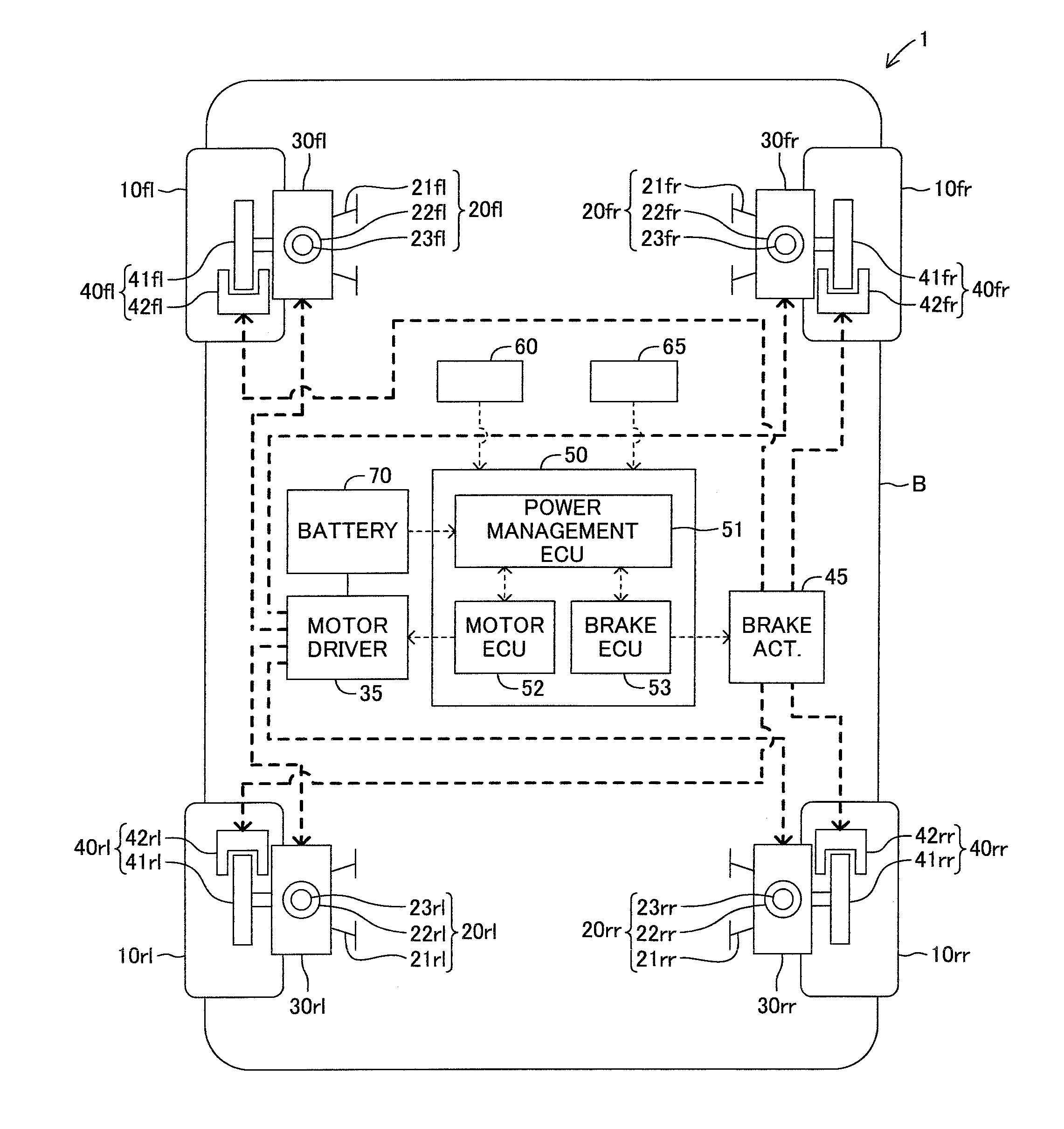
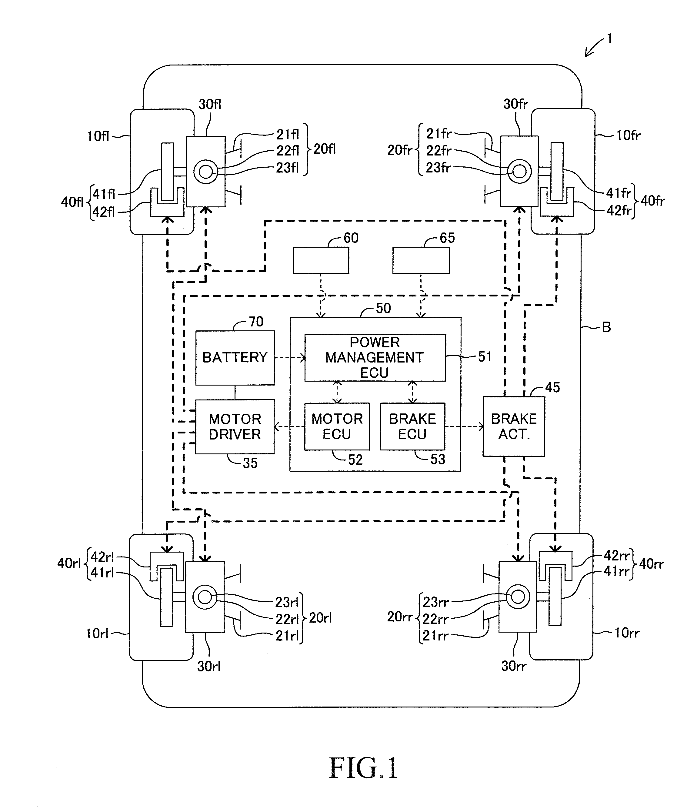
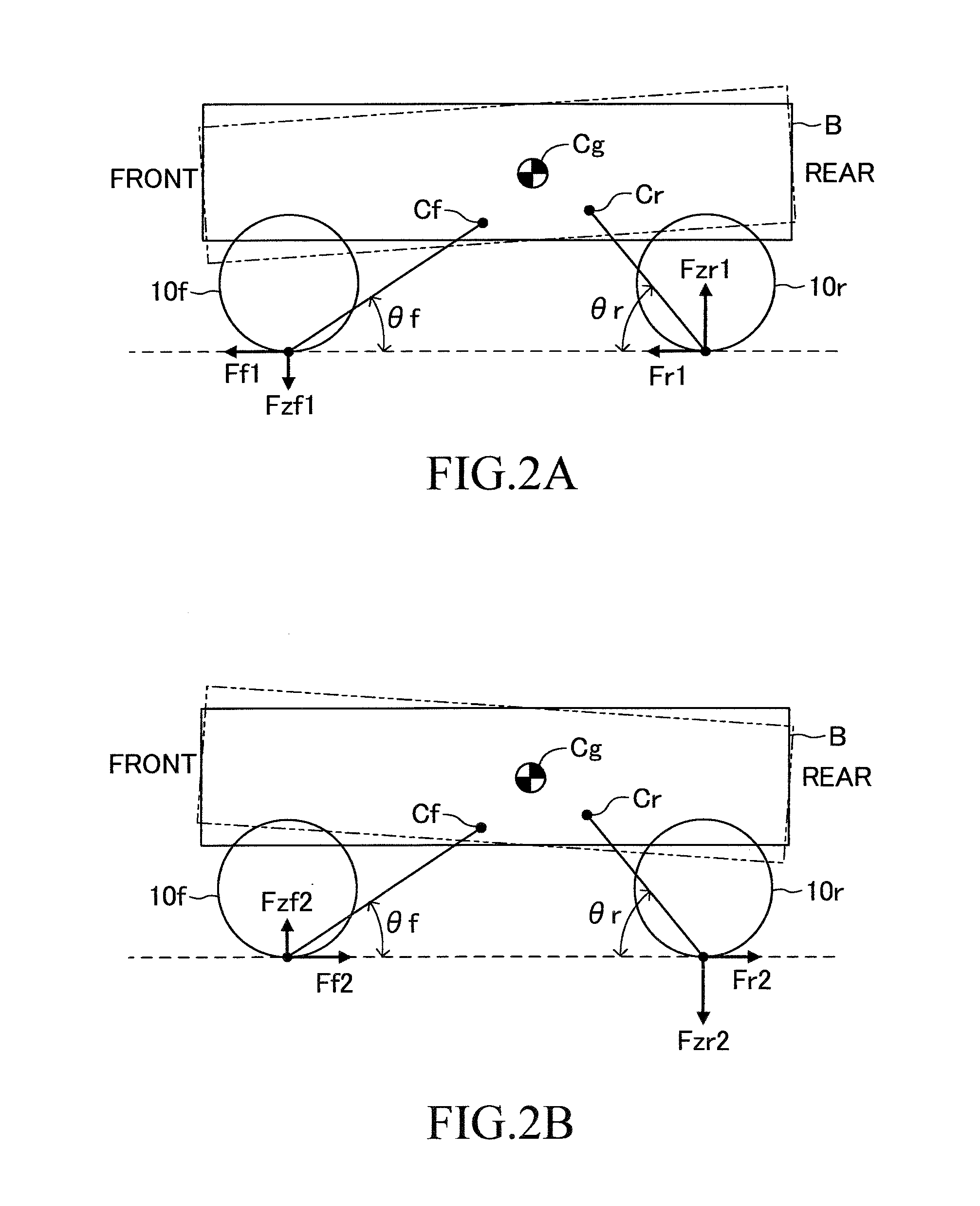
The present invention relates to a braking system for vehicles that can independently control braking and driving forces on each of the front / rear left / right wheels. This allows for better control of yaw motion, roll motion, pitch motion, and heave motion of the vehicle. Additionally, when the motor cannot provide enough braking and driving force for safe control, the system can shift the regenerative braking force to increase the margin for safe control. Overall, this system provides effective control of vehicle motion.

Problems solved by technology

There is a limit to regeneration performance.
Therefore, during the brake pedal operation, the control braking / driving force that can be generated by the motor, and can be used for the vehicle motion control is limited to a range acquired by excluding the requested regenerative braking force required for decelerating the vehicle from the maximum braking force that can be generated by the motor.
Under the state in which the margin of the control braking / driving force is decreased, the target driving force of the motor is liable to reach a performance limit, and satisfactory vehicle motion control may not be carried out.

Method used


Image

  • Braking force control apparatus for a vehicle
  • Braking force control apparatus for a vehicle
  • Braking force control apparatus for a vehicle

Examples


modified example 1

[0154]In the embodiment described above, the state flag fst is set based on the motion state or the operation state of the vehicle, but, in Modified Example 1, the state flag fst is set by further considering the usage rate of the motor torque. FIG. 10 and FIG. 11 are flowcharts for illustrating processing as Modified Example 1. FIG. 10 is a flowchart for illustrating a motor torque usage rate setting routine. FIG. 11 is a flowchart for illustrating a final state flag setting routine additionally reflecting a motor torque usage rate flag.

[0155]The brake ECU 53 starts the motor torque usage rate flag setting routine, and, in Step S121, calculates a motor torque usage rate A. In this case, the brake ECU 53 acquires, from the power ECU 51, data representing the target braking / driving torques of the four wheels and the braking torques that can be generated by the motors 30 currently calculated, and calculates the motor torque usage rate A based on the data. The target braking / driving to...

modified example 2

[0165]Under a state in which a grip force of the tire is approaching a limit during the braking, even when the driver-requested braking force is generated by the friction braking force to provide a margin for the vehicle motion control to the motor 30, satisfactory vehicle motion control cannot be carried out in the first place. Thus, in Modified Example 2, when this state is detected, by shifting the braking force that generates the driver-requested braking force from the friction braking force to the regenerative braking force, a kinetic energy, which was supposed to be lost by the friction braking, is converted into an electric energy, and is recovered to the battery 70.

[0166]FIG. 12 and FIG. 13 are flowcharts for illustrating processing as Modified Example 2. FIG. 12 is a flowchart for illustrating a slip rate flag setting routine. FIG. 13 is a flowchart for illustrating a final state flag setting routine additionally reflecting a slip rate flag.

[0167]The brake ECU 53 starts the...

modified example 3

[0179]Modified Example 2 may be combined with Modified Example 1. In this case, the brake ECU 53 executes the vehicle motion state determination flag setting routine illustrated in FIG. 9, the motor torque usage rate flag setting routine illustrated in FIG. 10, and the slip rate flag setting routine illustrated in FIG. 12 to calculate the vehicle motion state flag fstP, the motor usage state flag fstA, and the slip rate flag fstS. Then, the brake ECU 53 uses those three types of flags to execute a state flag setting routine illustrated in FIG. 15.

[0180]When the state flag setting routine (FIG. 15) starts, in Step S161, the brake ECU 53 determines whether or not the slip rate flag fstS is set to OFF. When the slip rate flag fstS is set to OFF (Yes in Step S161), in Step S162, the brake ECU 53 sets the state flag fst to OFF. On the other hand, when the slip rate flag fstS is set to ON (No in Step S161), in Step S163, the brake ECU 53 determines whether or not the vehicle motion state ...


PUM


Abstract

In order to enable satisfactory vehicle motion control to be carried out while wheels (10) are being braked, on a vehicle in which each of the wheels (10) is braked by a regenerative braking force by a motor (30) and a friction braking force by a friction brake mechanism (40), a brake ECU (53) acquires at least one parameter out of a steering angle, a steering velocity, a lateral acceleration of a vehicle body, a yaw rate of the vehicle body, a sprung vertical acceleration, and an unsprung vertical acceleration, and when a magnitude of the parameter is more than a threshold, decreases a ratio of the regenerative braking force out of a driver-requested braking force, and increases a ratio of the friction braking force.

Description

BACKGROUND OF THE INVENTION[0001]1. Field of the Invention[0002]The present invention relates to a braking force control apparatus for a vehicle, which is configured to brake a wheel by using both of a regenerative brake using an electric power generation operation of a motor and a mechanical brake using application of a mechanical resistance.[0003]2. Description of the Related Art[0004]Hitherto, there has been known a vehicle configured to use a motor to generate a driving force and a braking force (referred to as braking / driving force) on a wheel. In this type of vehicle, both of a friction braking force and a regenerative braking force are used to brake the wheel. The friction braking force is generated by using a hydraulic pressure to bring brake pads into contact with a disc (or a drum), and the regenerative braking force is generated by recovering electric power, which is generated by using the motor for driving the wheel to act as an electric power generator, to a battery. An...

Claims


Application Information

Patent Timeline
IPC IPC(8): B60L7/26B60L7/18B60T8/1761
CPCB60L7/26B60L7/18B60T8/17616B60L7/24B60L15/2009B60L2240/18B60L2240/24B60L3/10B60T1/10B60T8/1755B60T2270/604B60T2270/613Y02T10/64Y02T10/72
Inventor NAKATSU, MASATOSHI
Owner TOYOTA JIDOSHA KK
Why Eureka
Eureka Blog
Learn More