Heat-utilizing power generation battery and heat-utilizing power generation method using same

a technology of power generation battery and heat-utilizing power generation, which is applied in the direction of generator/motor, electrical apparatus, and thermoelectric device junction materials, etc., can solve the problems of high price of the semiconductors forming the thermoelectric conversion element, low conversion efficiency, and high operating temperature range, and achieve long-life, stable operation

Active Publication Date: 2021-09-23
TOKYO INST OF TECH +1
View PDF3 Cites 0 Cited by
  • Summary
  • Abstract
  • Description
  • Claims
  • Application Information

AI Technical Summary

Benefits of technology

[0014]According to the thermoelectric battery of the present invention, the heat-utilizing electric generation can be stably carried out. Further, according to one embodiment of the present invention, a long life thermoelectric battery can be obtained.

Problems solved by technology

However, the conventional thermoelectric conversion element using the temperature gradient has problems such as the high price of the semiconductors constituting the thermoelectric conversion element, the high operating temperature range, and the low conversion efficiency.
Further, there is a problem that a physical durability of a joint is weak and thus it cannot be installed in a place where vibration is applied.
Furthermore, since the electric generation requires the temperature gradient, the installation location is limited.
In other words, it has the disadvantage that all the surrounding heat cannot be used three-dimensionally and thus the heat utilization efficiency is low.

Method used


Image

  • Heat-utilizing power generation battery and heat-utilizing power generation method using same
  • Heat-utilizing power generation battery and heat-utilizing power generation method using same
  • Heat-utilizing power generation battery and heat-utilizing power generation method using same

Examples


example 1

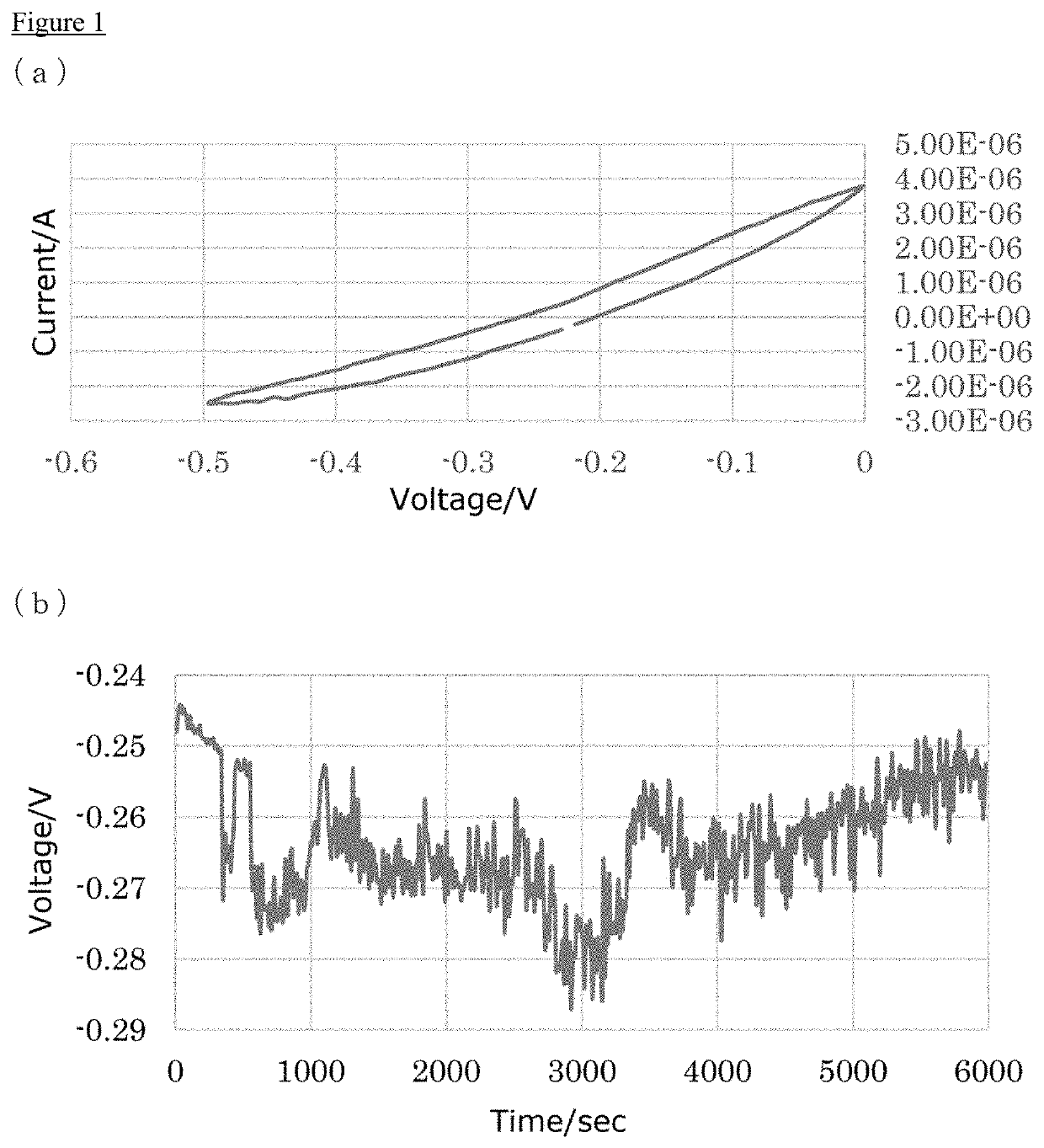
[0090]In this example, a thermoelectric cell was prepared using PEG600 as the solid electrolyte and CuCl as the ion source.

[0091]The following working electrode was used. 20 nanometers of Cr was deposited as a binder on n-Si having a thickness of about 0.5 mm, and 2 μm of Ge was deposited thereon, and it was cut into 25×15×0.5 mm.

[0092]As the counter electrode, fluorine-doped tin oxide (FTO, sheet resistance 7Ω / □, Aldrich) cut to a size of 25×15×2.2 mm was used.

[0093]The electrolyte was prepared by applying 0.1 g of PEG600 (Wako) in a mortar, adding CuCl (0.01 g), and stirring for 10 minutes. The resulting electrolyte (1 μL) was dropped onto the germanium of the working electrode. A thermally-resistant insulating double-sided tape (Kapton tape with 5 mm holes) was used as a spacer to bond the germanium side of the working electrode and the FTO of the counter electrode. That is, the electrode area of the power generation part was a circle with a diameter of 5 mm, i.e., 78.5 square mi...

example 2

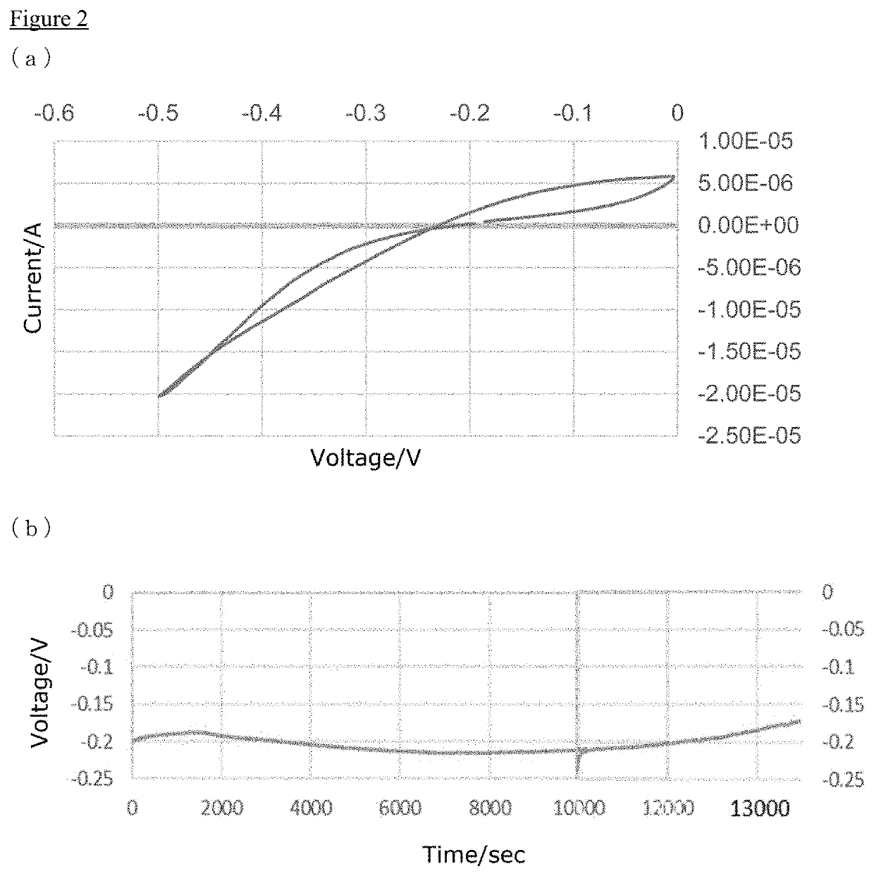
[0095]In this example, the procedure described in Example 1 was repeated except for using acetonitrile (ACN) as the additive, to prepare a thermoelectric cell.

[0096]0.1 g of PEG600 was applied in a mortar, and CuCl (0.01 g) and ACN (0.25 mL) as the additive were added thereto, and then ACN was evaporated by allowing to stand at 80° C. for 20 minutes, to prepare the electrolyte. The results are shown in Table 1 and FIG. 2.

[0097]Power generation characteristics with an open circuit voltage of about 0.2 V and a short-circuit current of about 5 microamperes were observed (FIG. 2a). A stable discharge at about 0.2V and 10 nanoamperes was continued for about 4 hours. (FIG. 2b).

example 3

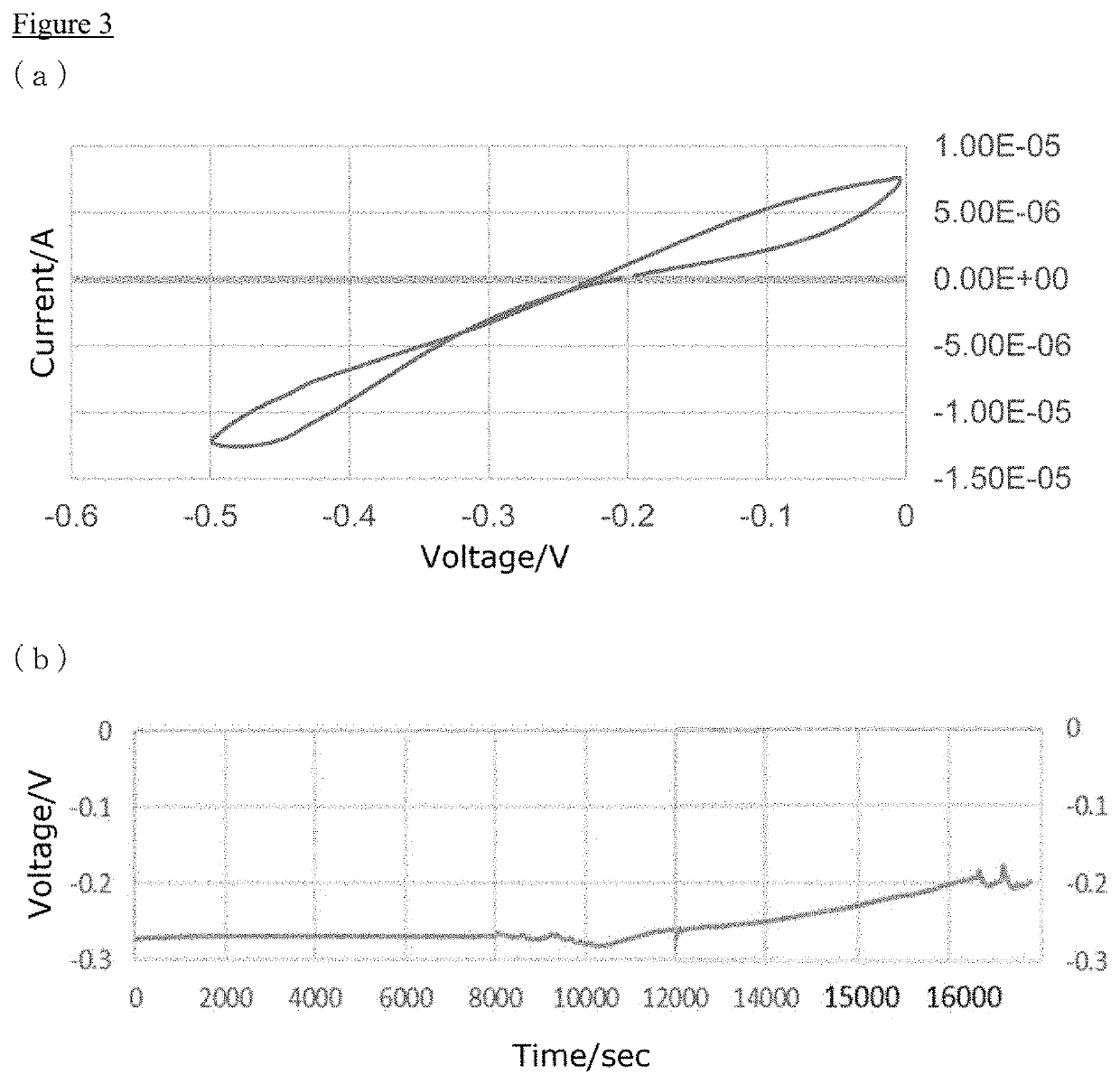
[0098]In this example, the procedure described in Example 2 was repeated except for using PEG2000 instead of PEG600 as the solid electrolyte, to prepare a thermoelectric cell.

[0099]0.1 g of PEG2000 was applied in a mortar, and CuCl (0.01 g) and ACN (0.5 mL) as the additive were added thereto, and the whole was stirred for 10 minutes at 80° C. ACN was evaporated by allowing to stand at 80° C. for 20 minutes, to prepare the electrolyte. The results are shown in Table 1 and FIG. 3.

[0100]Power generation characteristics with an open circuit voltage of about 0.2 V and a short-circuit current of 7 microamperes were observed (FIG. 3a). A stable discharge at 10 nanoamperes was continued for about 4.5 hours. (FIG. 3b).


PUM

PropertyMeasurementUnit
inner diameteraaaaaaaaaa
temperatureaaaaaaaaaa

Abstract

An object of the present invention is to provide a stable thermoelectric battery. The object can be solved by a thermoelectric battery comprising a working electrode containing a n-type silicon and germanium, a counter electrode, and a solid electrolyte having a polymer having a specific repeating unit with a molecular weight of 200 to 1,000,000, or a derivative thereof, wherein the solid electrolyte contains copper ions or iron ions as an ion source.

Description

TECHNICAL FIELD[0001]The present invention relates to a thermoelectric battery, and a process for generating thermoelectricity using the same. According to the present invention, it is possible to generate electricity efficiently by using heat.BACKGROUND ART[0002]Hitherto, a thermoelectric generation using the Seebeck effect has been known as heat-utilizing electric generation using geothermal heat or exhaust heat of factories (Patent literature 1 and 2, and Non-patent literature 1). It is expected to be put into practical use in order to efficiently use thermal energy. Thermoelectric generation by the Seebeck effect uses the power generation principle in which a voltage is generated when a temperature gradient is provided on a metal or a semiconductor. Specifically, in a thermoelectric generation system, thermal energy is converted into electrical energy by applying a temperature gradient to a thermoelectric conversion element in which a p-type semiconductor and an n-type semicondu...

Claims


Application Information

Patent Timeline
Patent Type & Authority Applications(United States)
IPC IPC(8): H01L35/24H02N3/00
CPCH01L35/24H02N3/00H10N10/856H10N15/00
Inventor MATSUSHITA, SACHIKOARAKI, TAKUMAMEI, BIAONISHIYAMA, JUNYA
Owner TOKYO INST OF TECH
Why Eureka
Try Eureka