
Intelligent water emergency system

a water emergency system and intelligent technology, applied in the direction of program control, electric programme control, instruments, etc., can solve the problems of millions of dollars in yearly losses for homeowners, business entities and insurance carriers, and drawbacks of the known water control system of the prior ar

Inactive Publication Date: 2016-06-09
MAX YAAKOV S
View PDF3 Cites 66 Cited by
  • Summary
  • Abstract
  • Description
  • Claims
  • Application Information

AI Technical Summary

Benefits of technology

The invention is a water emergency system that is designed to operate even if there is no electrical power available. It is powered by batteries to ensure that it can still be used in a crisis situation.

Problems solved by technology

When people are not at home, or just not aware of a broken pipe, the property losses can be huge.
It is a common occurrence that causes millions of dollars in yearly losses to homeowners, business entities and insurance carriers.
Still, there are drawbacks to the known water controlling systems of the prior art.
The prior art also does not take into account the likelihood that a water supply leak may happen as a result of a prolonged disruption of the electrical system which shuts down a building's heating plant during a cold winter, thereby causing freezing and plumbing damage.
During power outages, there is no way to communicate electronically and to provide electrical alerts to an owner of a home or a business, nor to actually control electronically the various water supply valves to effect shutting off of the water supply.
Another drawback of the prior art is that even where water sumps are provided to drain away water in a basement and the like, these water sumps are not electrically integrated with systems that control the water supply to the building.

Method used


Image

  • Intelligent water emergency system
  • Intelligent water emergency system
  • Intelligent water emergency system

Examples


Embodiment Construction

[0021]The concepts and instrumentalities that help mitigate the various drawbacks mentioned above can be appreciated from the instant drawings and the following descriptions, which refer to the drawings.

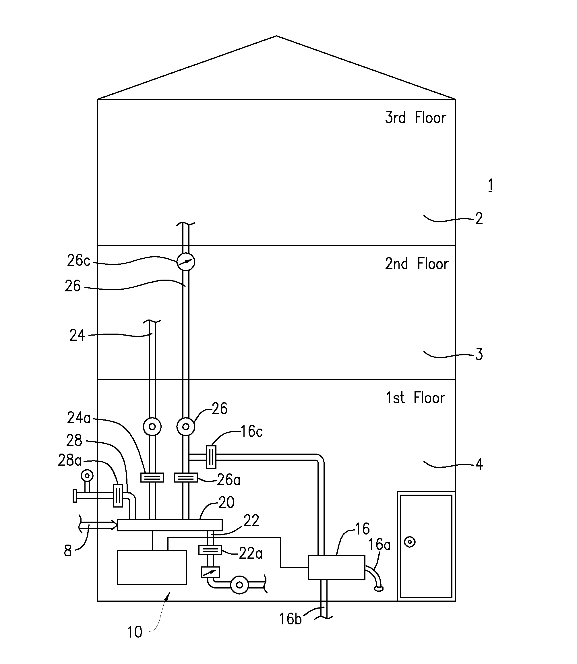
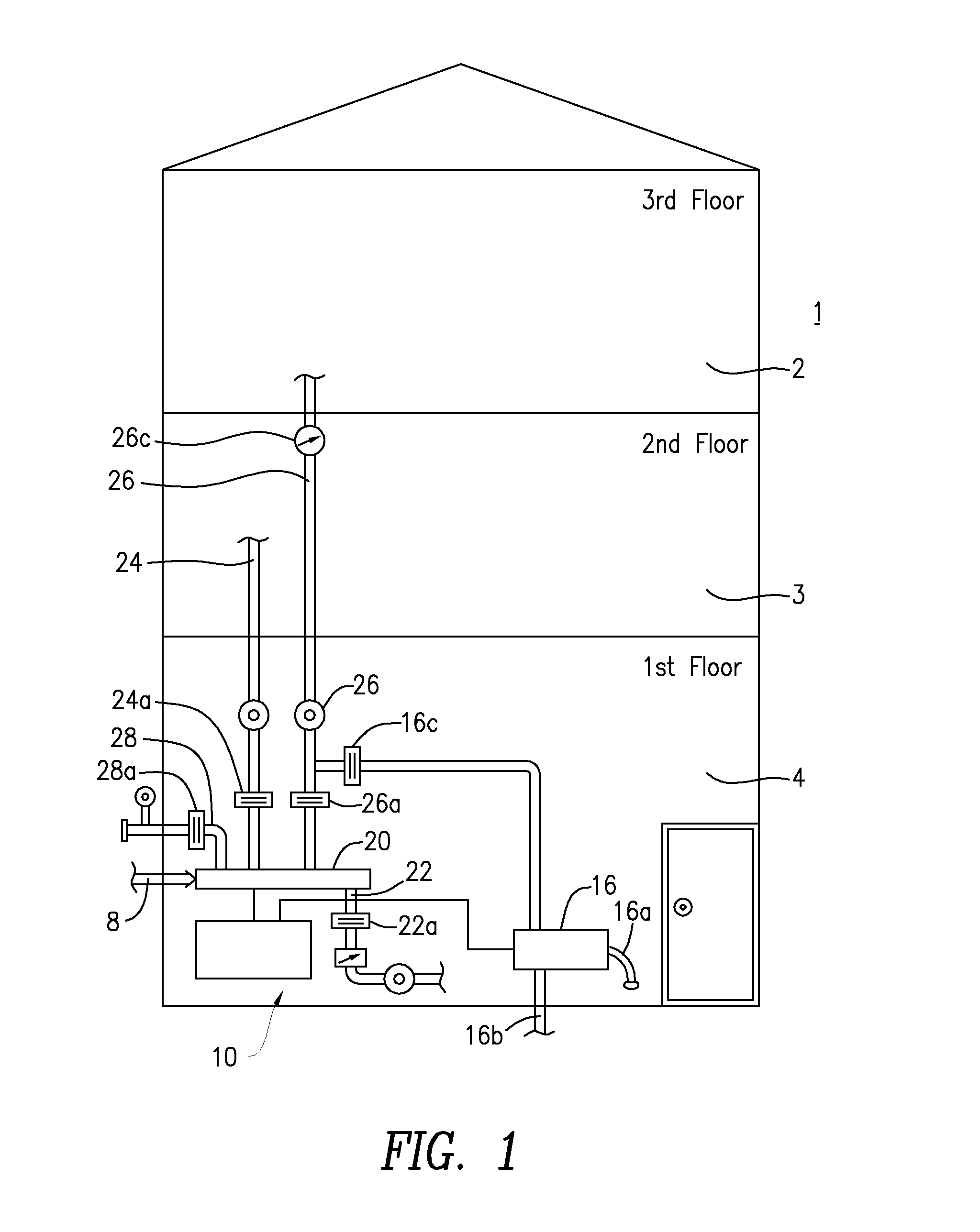
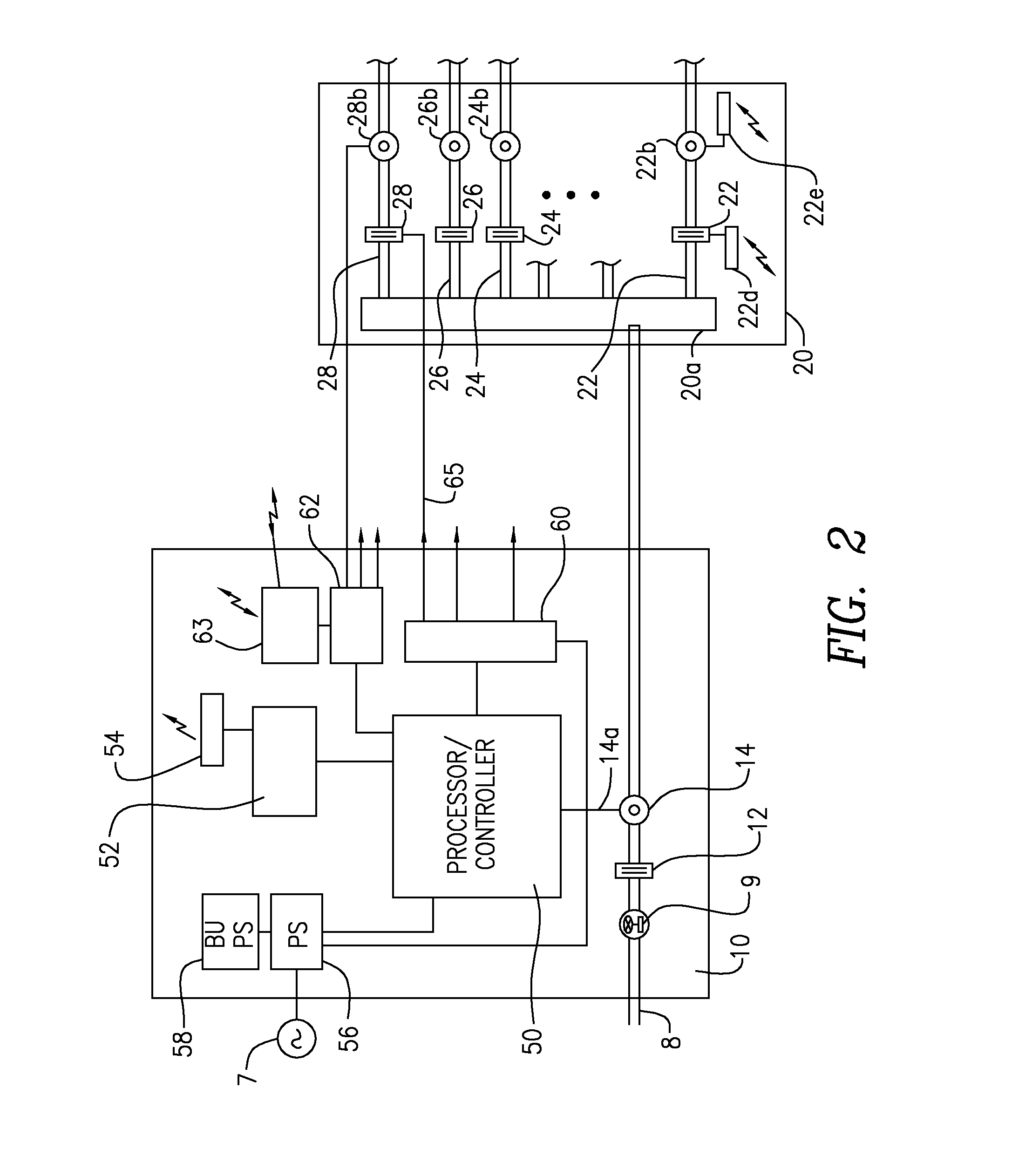
[0022]In FIG. 1, the home 1, which includes a third floor 2, a second floor 3 an a first floor 4, is outfitted with an electrical water control system 10, which is preferably located on the lowest floor, for example, the first floor 4. In accordance with the invention, the water utility provides the main water source through the main water pipe 8 which feeds the water manifold 20 which is controlled by the controller 10, in order to regulate the supplying of water to the various floors, as well as to the perimeter outside the home 1. To this end, the manifold 20 delivers water via a first water conduit 22 to the first floor, a second water conduit 24, a third water conduit 26 and a fourth water conduit 28. The water manifold 20 may contain a master electrical valve as described furth...


PUM


Abstract

An intelligent water flow control system is coupled with a main water flow source and controls the water flow by controlling an electrical valve in line with the water source and making a determination by receiving information from one or more water flow detectors. The system controller executes that software which issues information from the one or more flow detectors and output signals for controlling the open or closed state of the various valves. The software makes determinations on whether a leakage condition is present and issues the valve control signals to shut off the necessary valves and to report to a user, the occurrence of a leakage condition.

Description

BACKGROUND OF THE INVENTION[0001]The present invention is generally directed to water supply control systems and, more particularly, to an intelligent water control system for shutting off the water main, and optionally, subsidiary branches of the water plumbing at a home or a business automatically and optionally in direct response to wireless remote instructions from a user.[0002]As is well known, frozen pipes that thaw oftentimes flood homes or business establishments. Automatic water feeders that go bad do not stop running. Similarly, a broken hot water heater will continue spewing water flooding one's basement floor. Broken washer hoses and fridge lines do not stop running until found, and turned off. When people are not at home, or just not aware of a broken pipe, the property losses can be huge. It is a common occurrence that causes millions of dollars in yearly losses to homeowners, business entities and insurance carriers. There is a need for effective damage control to mit...

Claims


Application Information

Patent Timeline
Patent Type & Authority Applications(United States)
IPC IPC(8): G05B19/416G05D7/06
CPCG05B19/4166G05B2219/37371G05D7/0635F17D5/00F17D5/06G01M3/2807G08C2201/42G01M3/243G08C17/00H04Q9/00H04Q2209/60G08C2201/12E03B7/071Y02A20/15
Inventor MAX, YAAKOV S.
Owner MAX YAAKOV S
Learn More