Bone plate with elevated suture hole structures

a bone plate and structure technology, applied in the field of bone plates, can solve the problems of difficult suture passing, difficult adjustment of screws, and difficulty in passing sutures,

Inactive Publication Date: 2016-06-16
EXTREMITY DESIGNS
View PDF0 Cites 62 Cited by
  • Summary
  • Abstract
  • Description
  • Claims
  • Application Information

AI Technical Summary

Benefits of technology

[0008]In accord with another embodiment, the fastener hole of the bone plate comprises two or more sets of threads with intersecting axes, wherein the angle of each axis is predetermined during manufacturing.

Problems solved by technology

Problems arise when the plate is first attached to the bone since it is difficult to pass the sutures between the plate and the bone.
This solution still presents challenges during surgery as there is insufficient space or clearance between the bone plate and the bone.
Additionally, the superior screws often have the problem of exiting the humeral head superiorly, thus these screws must be able to be adjusted inferiorly to be directed completely into the humeral head.

Method used


Image

  • Bone plate with elevated suture hole structures
  • Bone plate with elevated suture hole structures
  • Bone plate with elevated suture hole structures

Examples


Embodiment Construction

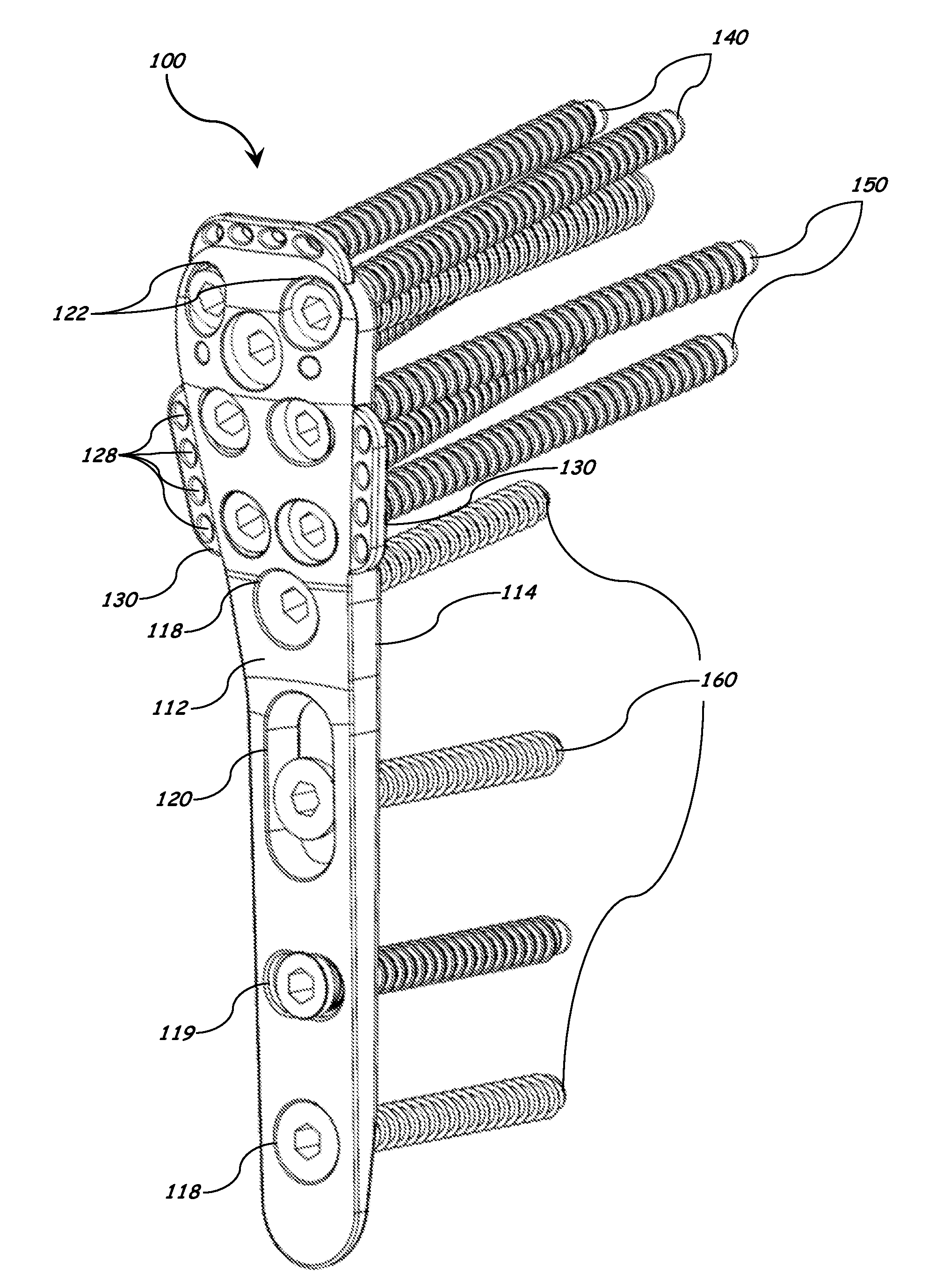
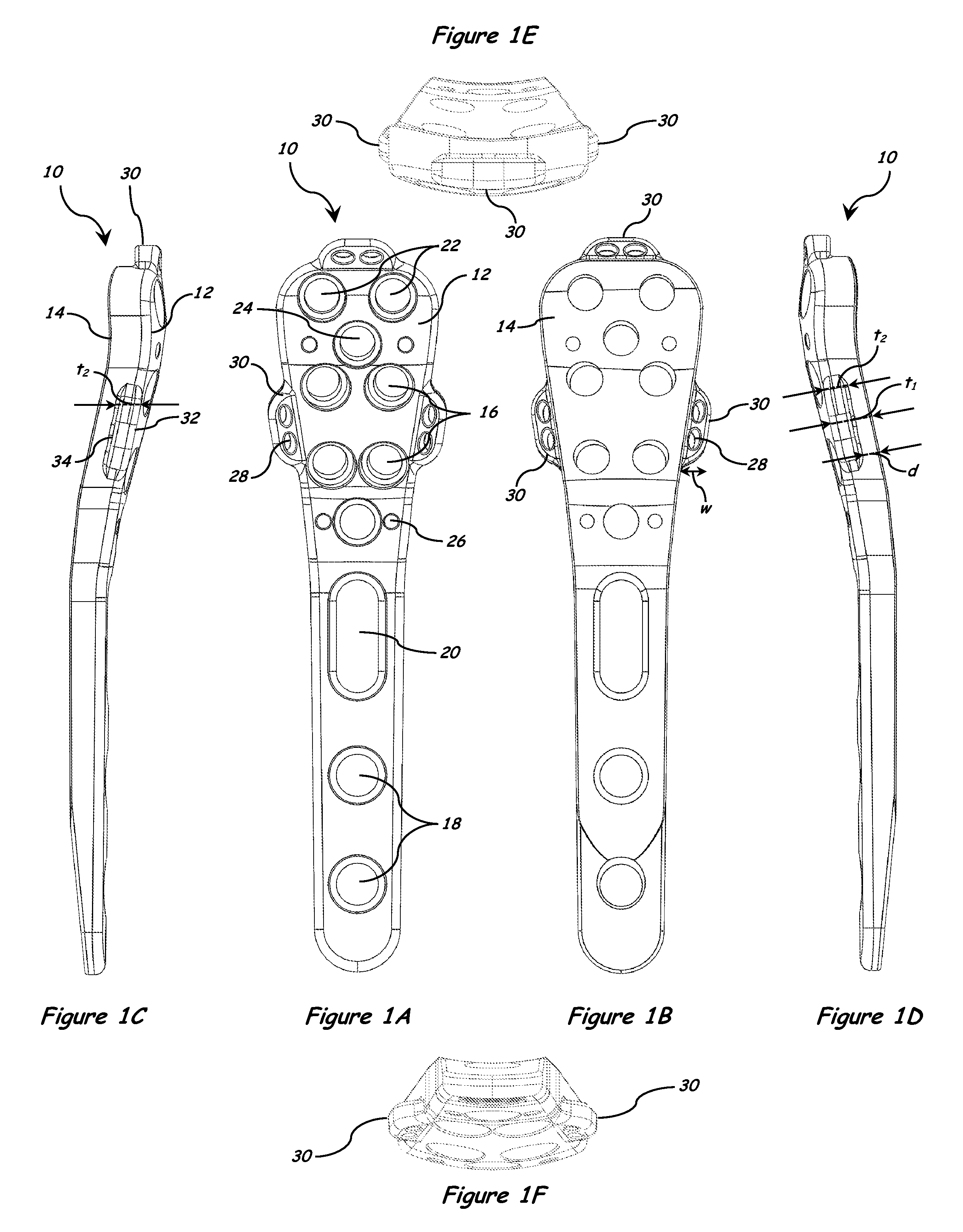
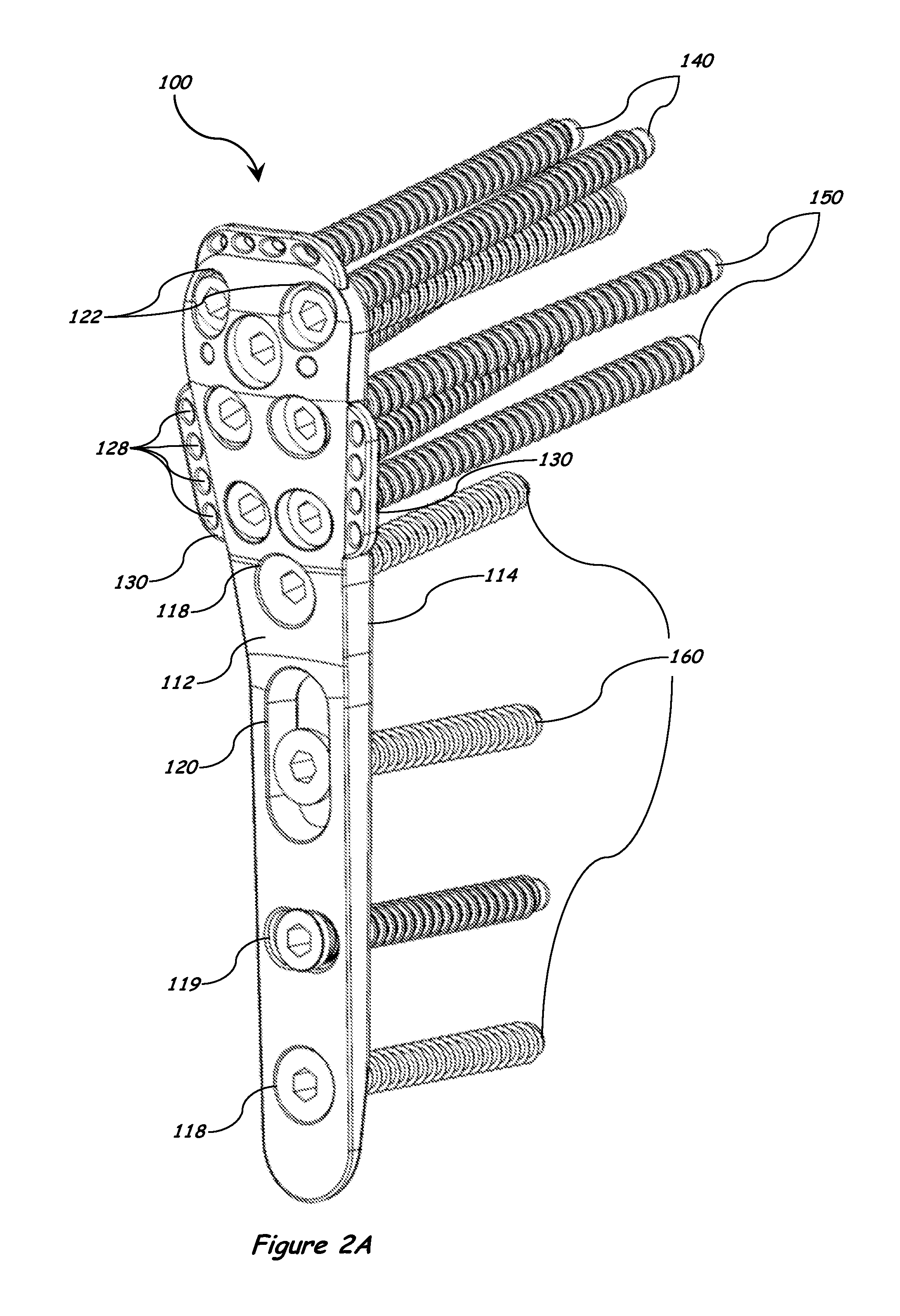
[0038]The following detailed description and the appended drawings describe and illustrate various bone plate systems, methods, and components. The description and drawings are exemplary in nature and are provided to enable one skilled in the art to make and use one or more exemplary bone plate systems and / or components, and / or practice one or more exemplary methods. They are not intended to limit the scope of the claims in any manner.

[0039]The use of “e.g.,”“etc.,”“for instance,”“in example,” and “or” and grammatically related terms indicates non-exclusive alternatives without limitation, unless otherwise noted. The use of “optionally” and grammatically related terms means that the subsequently described element, event, feature, or circumstance may or may not be present / occur, and that the description includes instances where said element, event, feature, or circumstance occurs and instances where it does not. The use of “exemplary” refers to “an example of” and is not intended to ...


PUM


Abstract

The present invention includes a bone fixation plate assembly comprising a bone plate and a plate compression device for internal fixation of bone and tissue. The bone plate includes a top surface and a bottom bone-facing surface, one or more fastener holes extending between the top surface and the bottom bone-facing surface for fasteners, and one or more suture cleats extending from at least a portion of a boundary of the bone plate and configured to have one or more sutures passed therethrough. In one embodiment, the bone plate has a suture cleat configured to be elevated above the bottom bone-facing surface of the bone plate by a distance of between about 1-5 mm for providing suturing clearance for a suturing instrument, for example.

Description

CROSS-REFERENCE TO RELATED APPLICATIONS[0001]The present application is a continuation-in-part of U.S. patent application Ser. No. 14 / 569,401, filed on Dec. 12, 2014, and entitled “Bone Plate with Elevated Suture Hole Structures” which claims the benefit of U.S. provisional patent application Ser. No. 61 / 712,257, filed Dec. 12, 2013, and entitled “Humeral Fracture Plate with Suture Hole Projections”. All of the foregoing applications are incorporated herein by reference in their entireties.FIELD OF INVENTION[0002]This invention relates to a bone plate for use in repairing bone fractures.BACKGROUND OF THE INVENTION[0003]Proximal humerus fractures are most commonly repaired with open reduction and internal fixation using plates and screws attached via bi-cortical or uni-cortical fixation. The preferred method to gain access to the fracture site is by making a large incision through the skin and muscles. Once the fracture has been exposed, the fragments of bone are approximated to the ...

Claims


Application Information

Patent Timeline
Patent Type & Authority Applications(United States)
IPC IPC(8): A61B17/80A61F2/40A61F2/32A61F2/38A61B17/04A61F2/30
CPCA61B17/8057A61B17/80A61B17/8061A61B17/0401A61B17/8019A61B2017/0464A61F2/32A61F2/38A61F2/40A61B2017/00004A61B2017/564A61F2/30
Inventor MIGHELL, MARK ALANGUTIERREZ, SERGIO
Owner EXTREMITY DESIGNS
Why Eureka
Try Eureka