Differential device

Inactive Publication Date: 2016-06-16
MUSA PRECISION IND CO LTD
View PDF0 Cites 14 Cited by
  • Summary
  • Abstract
  • Description
  • Claims
  • Application Information

AI Technical Summary

Benefits of technology

[0012]According to the first to third characteristics, the input member of the differential case includes the fitting hole opened in the outer side surface of the input member, the outer peripheral portion of the cover portion being fitted to the fitting hole. The cover portion fitted in the fitting hole and the support wall portion of the input member are joined together by the lap welding from outside of the cover portion, in the position separating inward in the radial direction of the input member from the fitting portion between the fitting hole and the cover portion. Thus, it is possible to inhibit an occurrence of the thermal strain due to the welding more effectively than when the input member and the cover portion are simply butt-welded together, and to thereby effectively prevent that assembling precision of the input member and the cover portion and accordingly the differential device as a whole decreases due to an influence of the thermal strain. Furthermore, the lap-welded portion is located inward of the fitting portion between the fitting hole and the cover portion in the rad

Problems solved by technology

Meanwhile, when the joined surfaces of the input part and the differential case are butt-welded together like in the conventional device, assembling precision of the input member and the differential case and accordingly the differential device as a whole may decrease to no small extent, because thermal strain tends to occur in a vicinity of the welded portions during the welding.
In addition, particularly in a case where a tooth portion as the input part is for

Method used


Image

  • Differential device
  • Differential device
  • Differential device

Examples


first embodiment

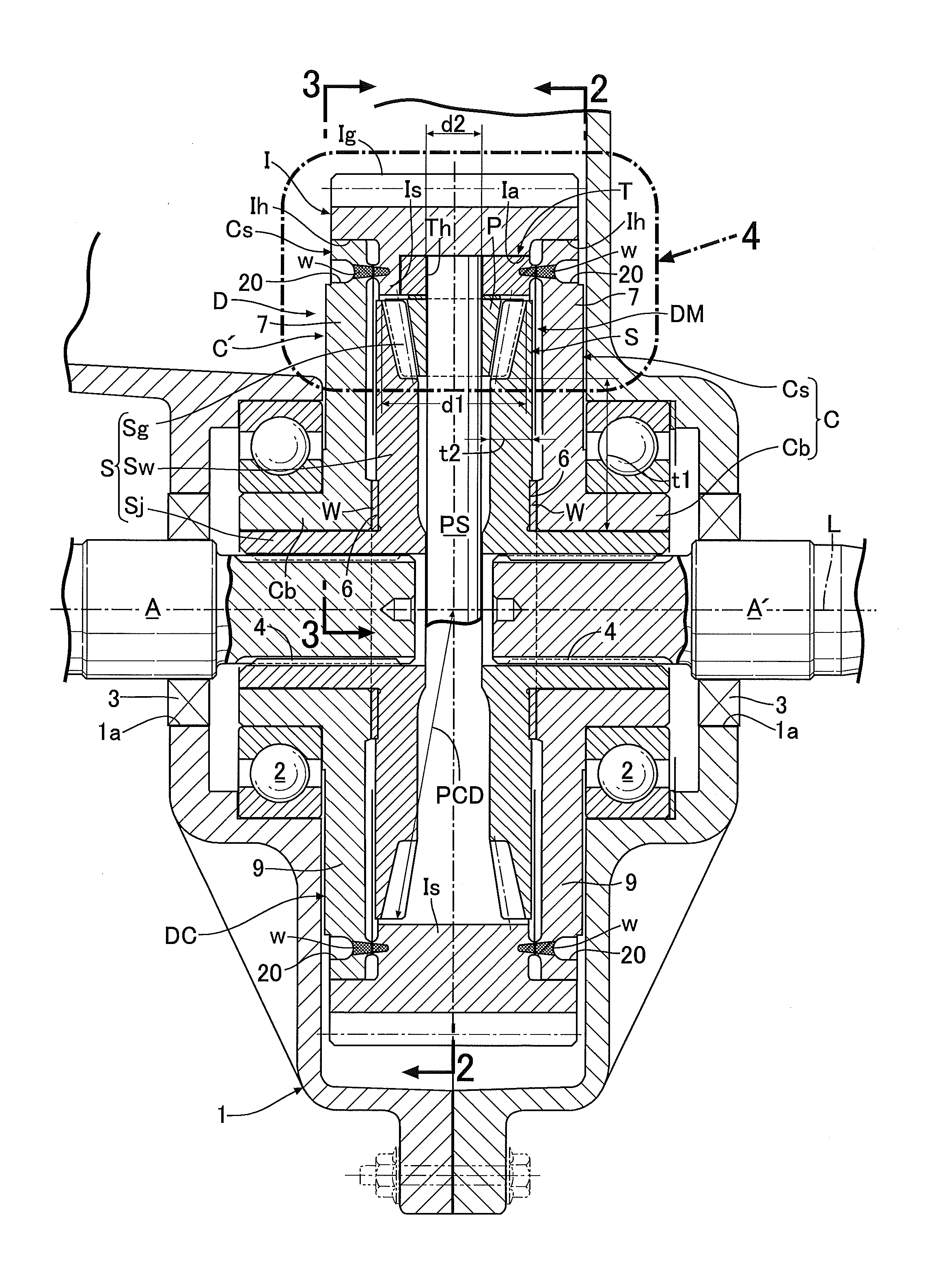
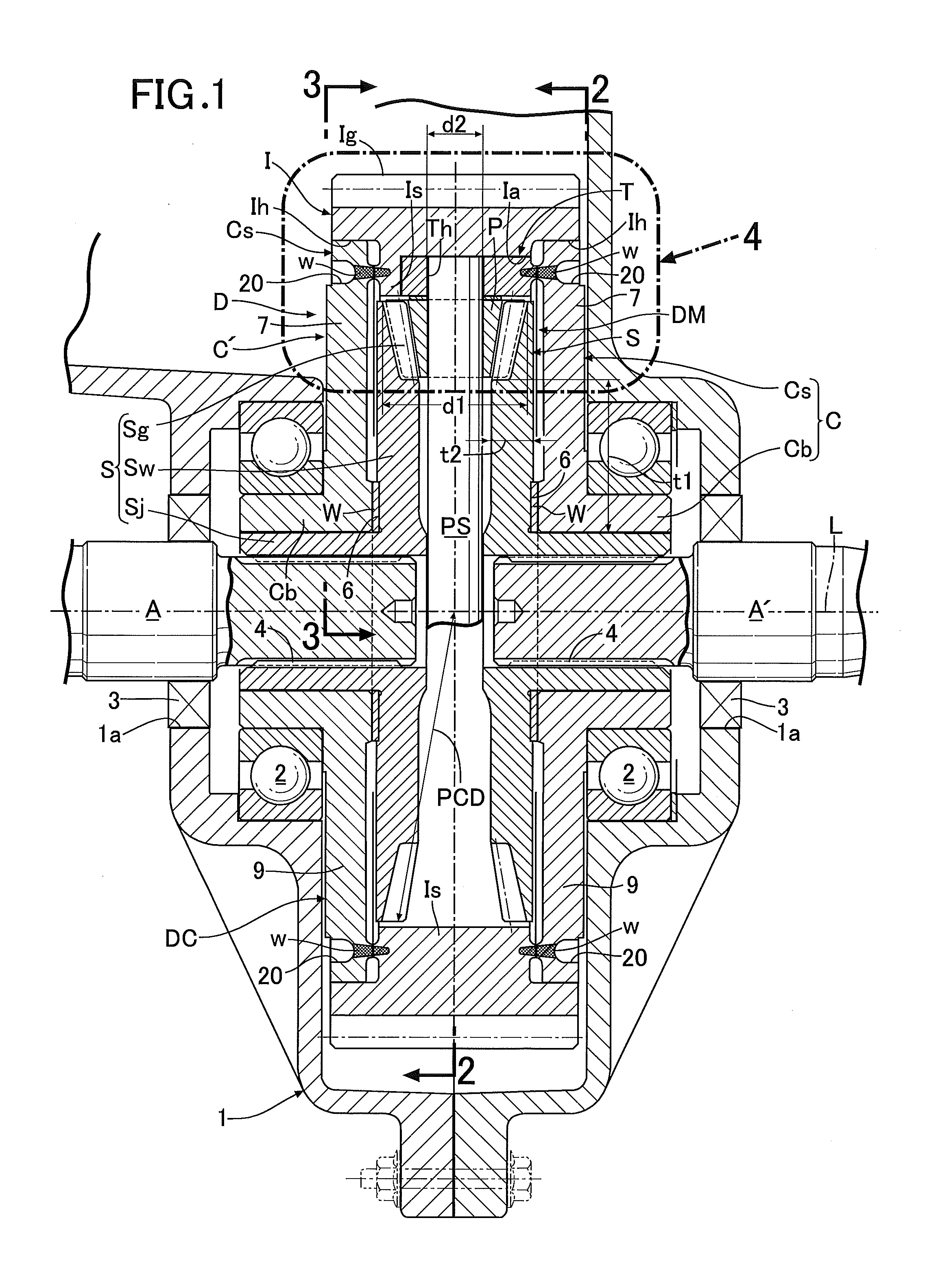
[0064]Next, descriptions will be provided for an operation of the In the differential device D of this embodiment, in a case where the input member I receives rotational force from the engine, when the pinion P revolves around the axis L of the input member I together with the input member I without rotating around the pinion shaft PS, the left and right side gears S are rotationally driven at the same speed, and their driving forces are evenly transmitted to the left and right output shafts A, A′. Meanwhile, when a difference in rotational speed occurs between the left and right output shafts A, A′ due to turn traveling or the like of the automobile, the pinion P revolves around the axis L of the input member I while rotating around the pinion shaft PS. Thereby, the rotational driving force is transmitted from the pinion P to the left and right side gears S while allowing differential rotations. The above is the same as the operation of the conventional differential device.

[0065]I...

second embodiment

[0073]Moreover, in this second embodiment, a bearing bush 12 as a bearing allowing relative rotations between the support shaft portion PS′ and the attachment body T is inserted between an outer peripheral surface of the support shaft portion PS′ and an inner peripheral surface of the retaining hole Th of the corresponding attachment body T into which the support shaft portion PS′ is inserted. Incidentally, the bearing may be formed from a needle bearing or the like. In addition, the bearing may be omitted so that the support shaft portion PS′ is directly fitted into the retaining hole Th of the attachment body T.

[0074]Next, referring to FIGS. 6 and 7, a third embodiment of the present invention will be described. A differential case DCX and a differential mechanism DMX housed inside the differential case DCX of the third embodiment are different in concrete structure and function from the differential case DC and the differential mechanism DM of the first and second embodiments.

[00...

third embodiment

[0080]Next, descriptions will be provided for an operation of the differential mechanism DMX of the differential device D of this For example, when temporarily fixing the input member I (the first rotary member) and rotating the one output shaft A, the main shaft portion 105a of the eccentric shaft 105 rotates and the second rotary member 106 in mesh with the inner teeth Ib of the input member I revolves around the first rotation axis X1 while rotating on the first eccentric shaft portion 105b. Meanwhile, the eccentric shaft 105 makes the second rotary member 106 and the third rotary member 107 revolve with the 180-degree phase shift therebetween, and the rotation of the second rotary member 106 is transmitted to the third rotary member 107 via the fourth rotary member 108. For these reasons, the revolution and the rotation of the second rotary member 106 is transmitted to the third rotary member 107 only by the 180-degree phase shift between the second rotary member 106 and the th...


PUM


Abstract

To prevent decrease in assembling precision of the differential device and enable avoiding decrease in transmission efficiency even when a tooth portion is formed in an outer peripheral portion of an input member. The differential device includes: a differential case; and a differential mechanism housed in the differential case and distributively transmitting rotational force of the differential case to a pair of mutually-independent output shafts. The differential case includes the input member including an input part which receives the rotational force, an end portion of the input member on at least one side in an axial direction thereof being opened, and at least one cover portion covering the opened end portion of the input member on the one side in the axial direction. The input member includes a fitting hole opened in an outer side surface of the input member, an outer peripheral portion of the cover portion being fitted in the fitting hole, and a support wall portion facing an inner side surface of the cover portion fitted in the fitting hole. The cover portion and the support wall portion are joined together by lap welding from outside of the cover portion, in a position separating inward in a radial direction of the input member from a fitting portion between the fitting hole and the cover portion.

Description

BACKGROUND OF THE INVENTION[0001]1. Field of the Invention[0002]The present invention relates to an improvement of a differential device, particularly the differential device which includes a differential case; and a differential mechanism housed in the differential case and distributively transmitting rotational force of the differential case to a pair of mutually-independent output shafts.[0003]2. Description of the Related Art[0004]As a conventional differential device, Japanese Patent No. 5509910, for example, has made known a differential device in which a differential case includes: an input member having an input part that receives rotational force and formed in a cylindrical shape, an end portion of the input member on at least one side in an axial direction thereof being opened; and at least one cover portion covering the opened end portion of the input member. In the conventional device, an inner peripheral portion of a driven gear as the input part and an outer peripheral...

Claims


Application Information

Patent Timeline
IPC IPC(8): F16H48/40F16H48/08
CPCF16H48/08F16H48/40
Inventor YANASE, YOICHIMORI, HIROYUKI
Owner MUSA PRECISION IND CO LTD
Why Eureka
Try Eureka