Heatspreader with extended surface for heat transfer through a sealed chassis wall

a heat exchanger and chassis wall technology, applied in indirect heat exchangers, semiconductor/solid-state device details, lighting and heating apparatus, etc., can solve the problems of ineffective heat dissipation, inefficient heat dissipation of components, and increased problems

Inactive Publication Date: 2016-06-16
ABACO SYST INC
View PDF25 Cites 3 Cited by
  • Summary
  • Abstract
  • Description
  • Claims
  • Application Information

AI Technical Summary

Benefits of technology

[0014]The embodiments of the present invention facilitate bypassing of wedgelock thermal resistance and provide improved spreading resistances. These features ultimately result in a higher power dissipation capability of the circuit. They also reduce ambient to junction thermal temperatures of the heat source, or other heat dissipating electronic components, which enhances overall system reliability.

Problems solved by technology

As the footprint of electronic components continues to decrease, enabling greater numbers of components to be placed on a printed circuit board (PCB), efficiently dissipating heat produced by the components becomes more challenging.
This problem is amplified as even more of these PCBs with higher power components are housed within a single enclosure, or chassis.
But as the performance demands of these electronic components continues to increase, the traditional heat dissipating approaches become more inefficient and less effective.
This ineffectiveness is particularly true in instances where the chassis is sealed from the external environment, which is most often the case where the chassis is used as a line replaceable units (LRU).
The aforementioned conventional approach, however, is inefficient and suboptimal.
The inefficiencies of this approach render it inadequate to dissipate the massive amounts of heat that accumulate inside of a sealed chassis housing for cutting edge high-performance electronic systems available today.
These approaches, however, are not designed for use within a sealed system or chassis due to the absence of flow through the system.
The conventional system 100 is therefore limited in its utility to dissipate heat created by high performance electronic components housed within modern LRU sealed enclosures.

Method used


Image

  • Heatspreader with extended surface for heat transfer through a sealed chassis wall
  • Heatspreader with extended surface for heat transfer through a sealed chassis wall
  • Heatspreader with extended surface for heat transfer through a sealed chassis wall

Examples


Embodiment Construction

[0024]While the present invention is described herein with illustrative embodiments for particular applications, it should be understood that the invention is not limited thereto. Those skilled in the art with access to the teachings provided herein will recognize additional modifications, applications, and embodiments within the scope thereof and additional fields in which the invention would be of significant utility.

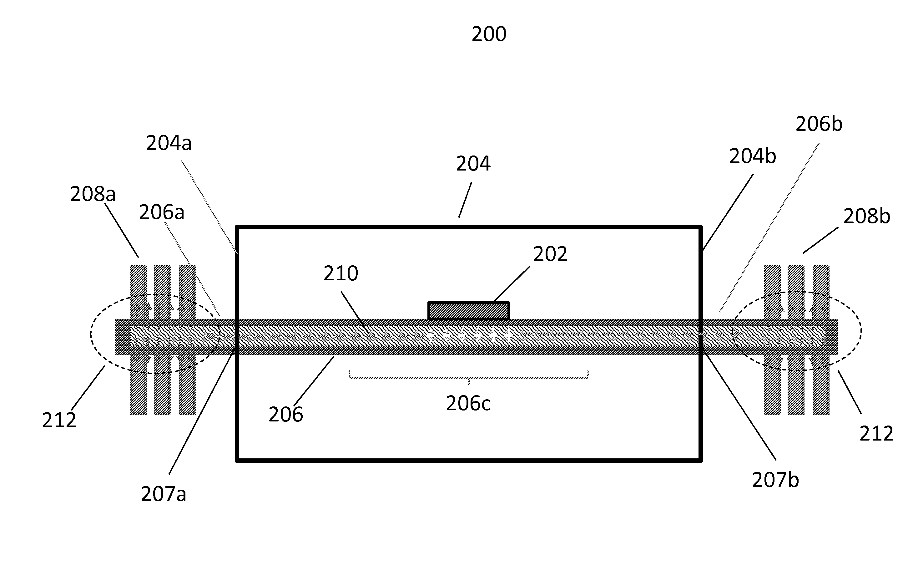
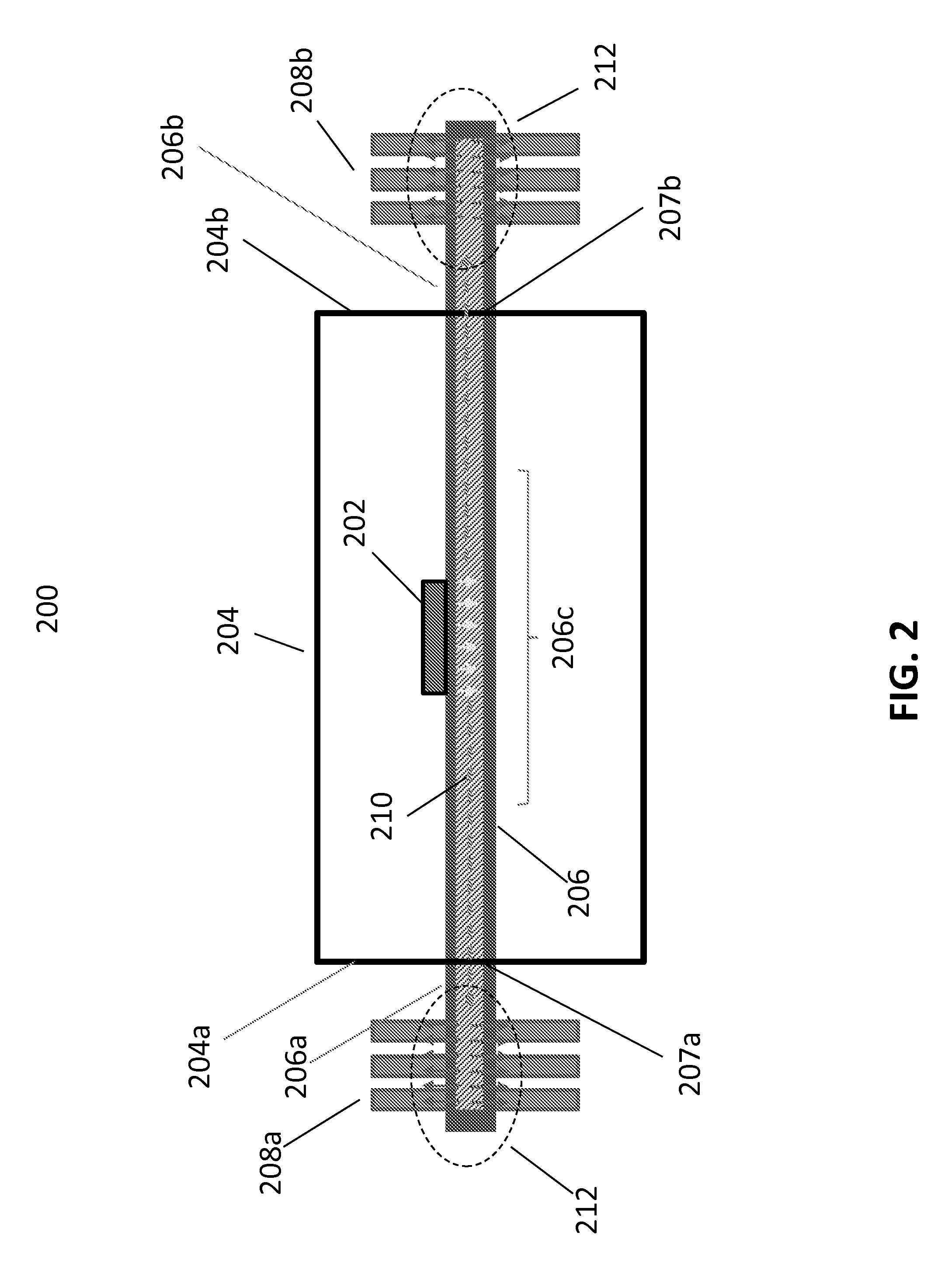
[0025]As discussed above, embodiments of the present invention provide a system for dissipating heat within an enclosure. By way of example, and not limitation, the embodiments can include a heat frame, or other efficient thermal connection, between the heat dissipating electronic components on the PCB. An efficient thermal connection is provided from the electronic components, to a heat transfer mechanism, such as heat pipes, through a wall opening of an LRU, to a heat rejection surface, such as a heat sink.

[0026]The embodiments also encompass a variety of different ...


PUM


Abstract

A system for cooling electronic components. The system includes tubing having a central portion attachable to a heat source disposed within a sealed enclosure. Distal portions of the tubing extend outside the enclosure through walls thereof. The system also includes fins attachable to the distal portions.

Description

CROSS-REFERENCE TO RELATED APPLICATIONS[0001]This application is a national stage application under 35 U.S.C. §371(c) of prior filed, co-pending PCT application serial number PCT / US2013 / 052488, filed on Jul. 29, 2013, and titled “HEATSPREADER WITH EXTENDED SURFACE FOR HEAT TRANSFER THROUGH A SEALED CHASSIS WALL”. The above-listed application is herein incorporated by reference.TECHNICAL FIELD[0002]Embodiments of the invention relate generally to heat dissipation within an enclosure. More specifically, embodiments of the invention relate to dissipating heat produced by an electronic component mounted on a circuit board within a sealed enclosure.BACKGROUND OF THE INVENTION[0003]As the footprint of electronic components continues to decrease, enabling greater numbers of components to be placed on a printed circuit board (PCB), efficiently dissipating heat produced by the components becomes more challenging. This problem is amplified as even more of these PCBs with higher power componen...

Claims


Application Information

Patent Timeline
Patent Type & Authority Applications(United States)
IPC IPC(8): F28F9/013F28D5/00H05K7/20F28F9/00
CPCF28F9/0138H05K7/20336F28D5/00F28F9/002F28D15/0275H01L23/427F28D2015/0216H05K7/20672H01L2924/0002H01L2924/00
Inventor DE BOCK, HENDRIK PIETER JACOBUSCHAMARTHY, PRAMODCHAUHAN, SHAKTI SINGHDENG, TAOHODEN, BRIANWEAVER, STANTON EARL
Owner ABACO SYST INC
Why Eureka
Try Eureka