Systems And Methods For Determining Free Plasma Hemoglobin

Active Publication Date: 2016-06-23
FENWAL
View PDF1 Cites 3 Cited by
  • Summary
  • Abstract
  • Description
  • Claims
  • Application Information

AI Technical Summary

Benefits of technology

[0012]In yet another aspect, a fluid separation system is provided for separating a plasma-containing fluid into separated plasma and a concentrated fluid. The fluid separation system is configured to cooperate with a fluid flow circuit including a fluid separation chamber and a plasma outlet line associated with the fluid separation chamber for removing separated plasma from the fluid separation chamber. An optical sensor assembly of the system is configured to monitor the contents of the plasma outlet line and produce an output indicative of the concentration of free plasma hemoglobin in the plasma outlet line. A controller of the system is programmed to calculate the free plasma hemoglobin concentration of the contents of the plasma outlet line based at least in part on the output of the optical sensor assembly. The controller includes a pre-programmed reference equation having one or more constants and representing an experimentally determined relationship between the output of the optical sensor assembly and free plasma hemoglobin concentration. The controller is programmed to, during a calibration test, generate an equation having one or more constants and representing the actual relationship between the output of the optical sensor assembly and free plasma hemoglobin concentration. The controller compares at least one of the constants of the reference equation to the corresponding constant or constants of the generated equation and registers the optical sensor assembly as having passed the calibration test if the differences between the corresponding constant or constants of the two equations are less than a predetermined tolerance away from each other. On the other hand, if the corresponding constant or constants of the two equations are greater than a predetermined tolerance away from each other, then the controller registers

Problems solved by technology

However, experience has shown that the concentration of free plasma hemoglobin in the plasma varies over time, and that a high free plasma hemoglobin concentratio

Method used


Image

  • Systems And Methods For Determining Free Plasma Hemoglobin
  • Systems And Methods For Determining Free Plasma Hemoglobin
  • Systems And Methods For Determining Free Plasma Hemoglobin

Examples


Embodiment Construction

[0021]The embodiments disclosed herein are for the purpose of providing an exemplary description of the present subject matter. They are, however, only exemplary, and the present subject matter may be embodied in various forms. Therefore, specific details disclosed herein are not to be interpreted as limiting the subject matter as defined in the accompanying claims.

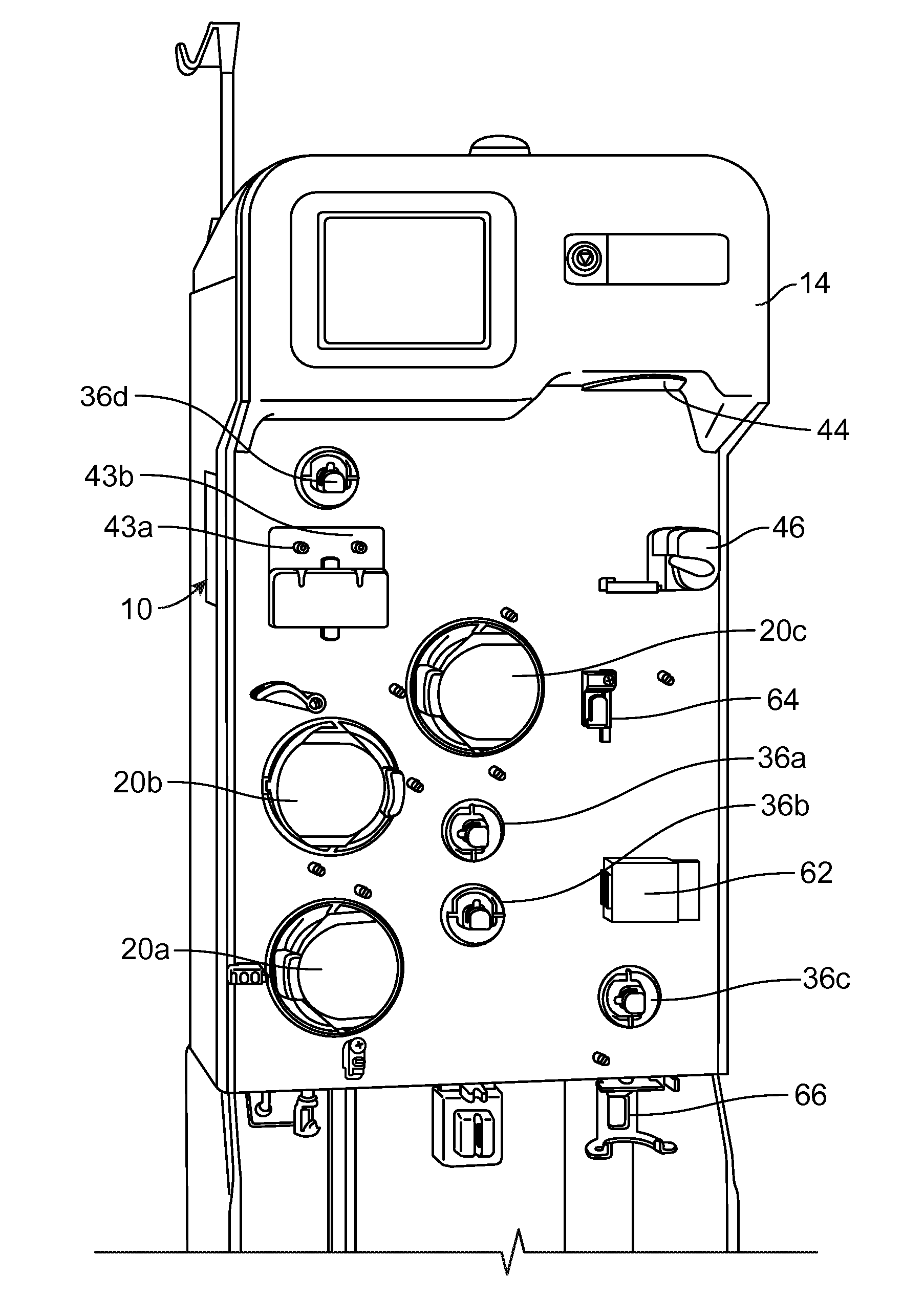
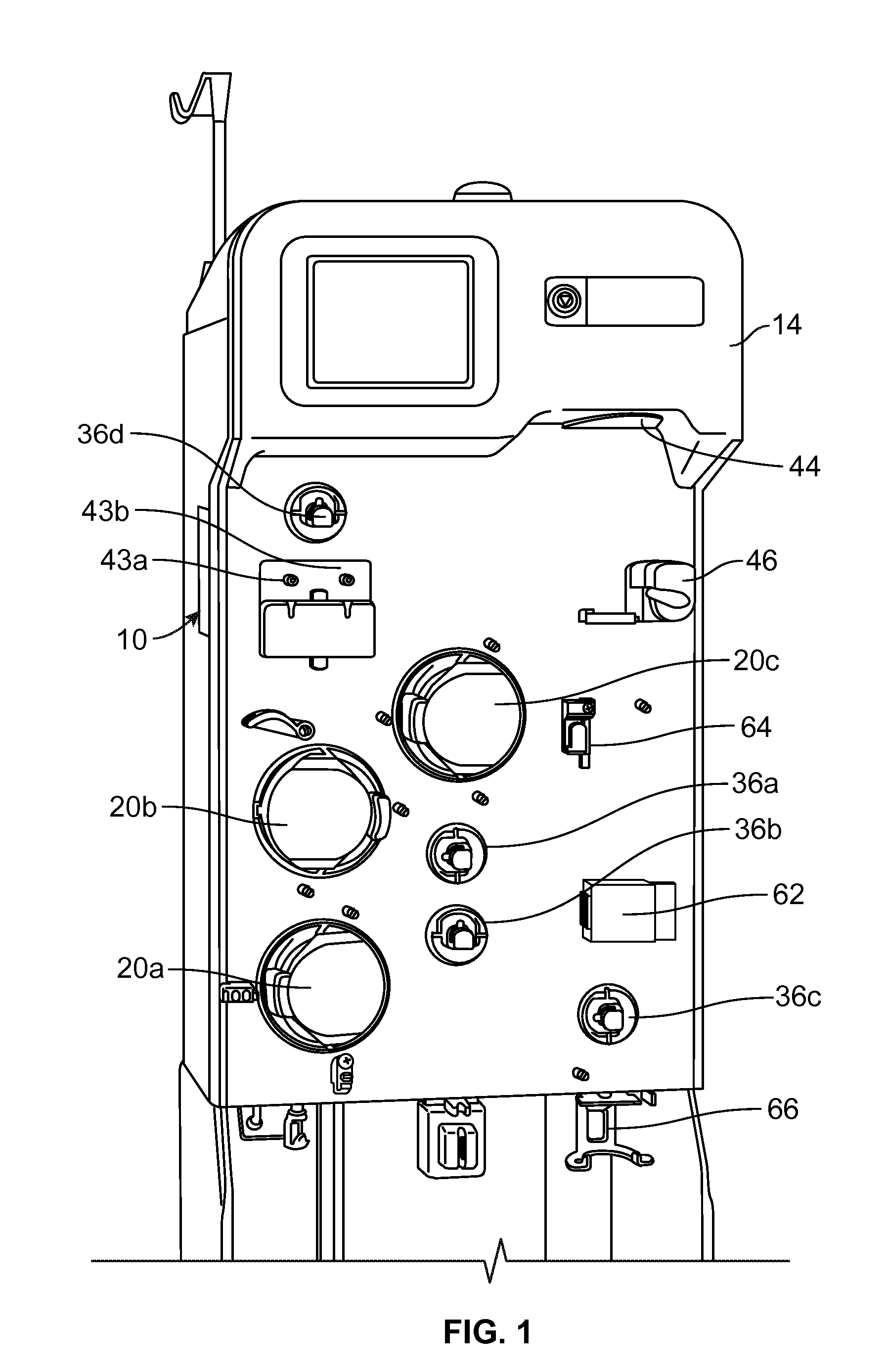
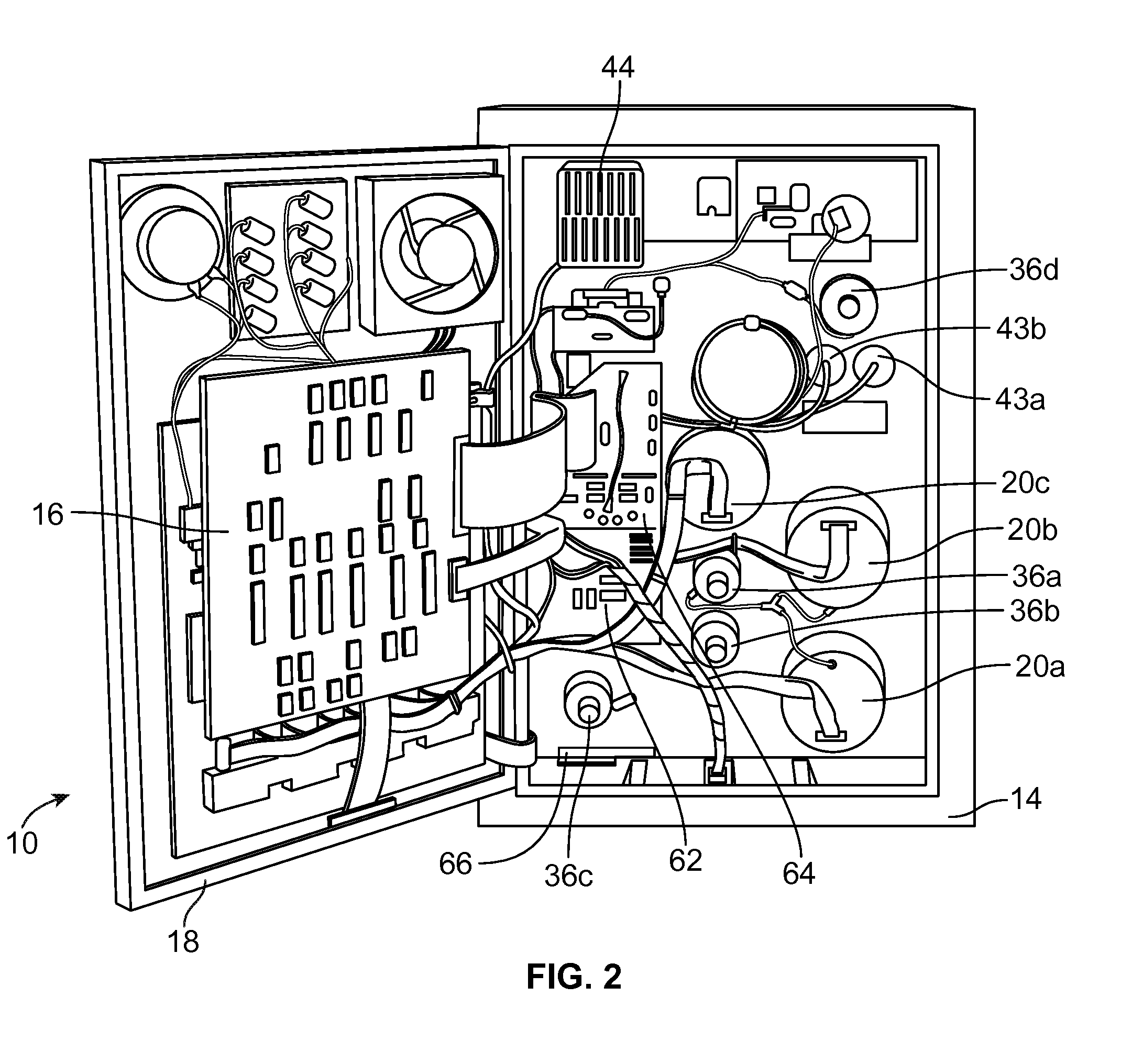
[0022]According to an aspect of the present disclosure, a durable or reusable fluid separation system is used in combination with a separate fluid flow circuit (which may be disposable) to separate a plasma-containing fluid into separated plasma and a concentrated fluid. FIGS. 1 and 2 illustrate an exemplary fluid separation system 10, while FIG. 3 illustrates an exemplary fluid flow circuit 12 mounted onto the fluid separation system 10, but it should be understood that the illustrated fluid separation system 10 and fluid flow circuit 12 are merely exemplary of such systems and circuits and that differently configured fl...


PUM


Abstract

A system is provided for separating a plasma-containing fluid into separated plasma and a concentrated fluid. The system cooperates with a fluid flow circuit including a fluid separation chamber and a plasma outlet line associated therewith for removing separated plasma from the fluid separation chamber. The system includes an optical sensor assembly to monitor the contents of the plasma outlet line and produce an output indicative of the concentration of free plasma hemoglobin in the plasma outlet line. A controller of the system calculates the amount of free plasma hemoglobin in at least a portion of the concentrated fluid based at least in part on the output of the optical sensor assembly. The controller may periodically calibrate the optical sensor assembly by determining an instrument-specific correlation between optic output and free hemoglobin concentration and comparing it to experimentally determined data to ensure continued reliability of the optical sensor assembly.

Description

BACKGROUND[0001]1. Field of the Disclosure[0002]The invention relates to fluid separation systems and methods. More particularly, the invention relates to systems and methods for detecting free plasma hemoglobin in plasma separated out of a plasma-containing fluid.[0003]2. Description of Related Art[0004]Various blood processing systems now make it possible to collect particular blood constituents, instead of whole blood, from a blood source such as, but not limited to, a container of previously collected blood or other living or non-living source. Typically, in such systems, whole blood is drawn from a blood source, the particular blood component or constituent is separated, removed, and collected, and the remaining blood constituents are returned to the blood source. Removing only particular constituents is advantageous when the blood source is a human donor, because potentially less time is needed for the donor's body to return to pre-donation levels, and donations can be made at...

Claims


Application Information

Patent Timeline
IPC IPC(8): A61M1/38A61M1/36A61M1/26G01N21/59A61M1/34
CPCA61M1/38G01N21/59A61M1/3406A61M1/265A61M1/3672G01N2201/12A61M2230/20A61M2205/3327A61M2205/331A61M2205/18A61M2202/0415A61M2205/702A61M2202/0443A61M2205/75G01N33/721G01N33/491A61M1/3496A61M1/3616G01N21/25
Inventor THILL, MELISSA A.PLANAS, SAMANTHA M.PATEL, AMIT J.MOORE, COURTNEYCORK, WILLIAM H.
Owner FENWAL
Why Eureka
Try Eureka