Vane structure for axial flow turbomachine and gas turbine engine

a technology of axial flow turbomachines and gas turbine engines, which is applied in the direction of liquid fuel engines, vessel construction, marine propulsion, etc., can solve the problems of reducing efficiency, deceleration regions, and uniform effect not necessarily obtained in a whole region in the vane radial direction, so as to enhance efficiency and enhance efficiency. , the effect of reducing secondary flow

Inactive Publication Date: 2016-06-23
IHI CORP
View PDF1 Cites 10 Cited by
  • Summary
  • Abstract
  • Description
  • Claims
  • Application Information

AI Technical Summary

Benefits of technology

[0018]According to the vane structure for the axial flow turbomachine and the gas turbine engine according to the present disclosure, a load of a deceleration region in a trailing edge portion of the vane that causes reduction in efficiency can be distributed to the front vane and the rear vane of the tandem vane, the deceleration region as the whole vane can be reduced, and enhancement in efficiency can be achieved.
[0019]In addi...

Problems solved by technology

In this case, separation of boundary layer may be generated due to the deceleration region to thereby cause reduction in efficiency, or a secondary flow (a flow having a turning component of a direction different from a main flow of gas) may be generated.
Therefore, there is a problem in which the position of the maximum velocity tends to be located more forward than the trailing edge to thereby cause a deceleration region.
However, as described above, since the velocity ratios on the one end side and the other end side in the vane radial direction are different from each other, a uniform effect is not ...

Method used


Image

  • Vane structure for axial flow turbomachine and gas turbine engine
  • Vane structure for axial flow turbomachine and gas turbine engine
  • Vane structure for axial flow turbomachine and gas turbine engine

Examples


Embodiment Construction

[0026]Hereinafter, one embodiment of the present disclosure will be explained in detail with reference to accompanying drawings. Dimensions, materials, other specific numerical values, and the like shown in such an embodiment are merely exemplification for facilitating understanding of the disclosure, and do not limit the present disclosure. Note that, in the specification and the drawings, overlapping explanation of elements having substantially the same functions and configurations is omitted by attaching the same symbols to the elements, and that illustration of elements having no direct relation to the present disclosure is omitted.

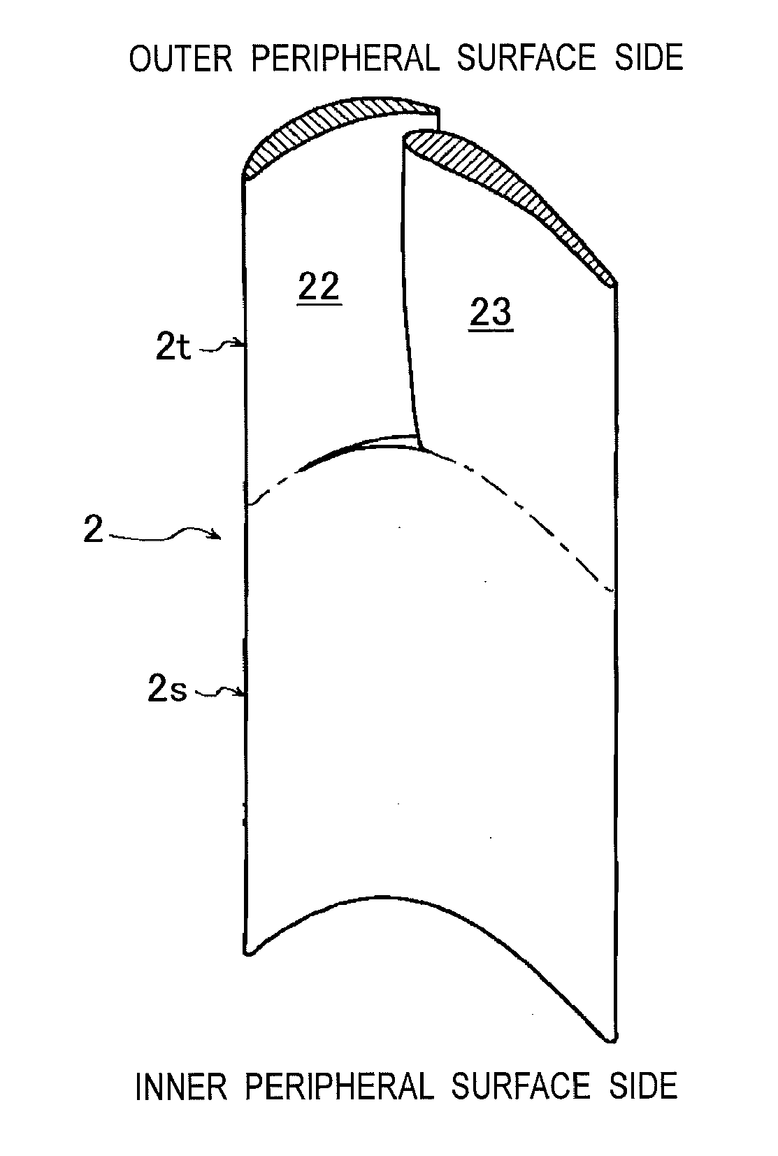
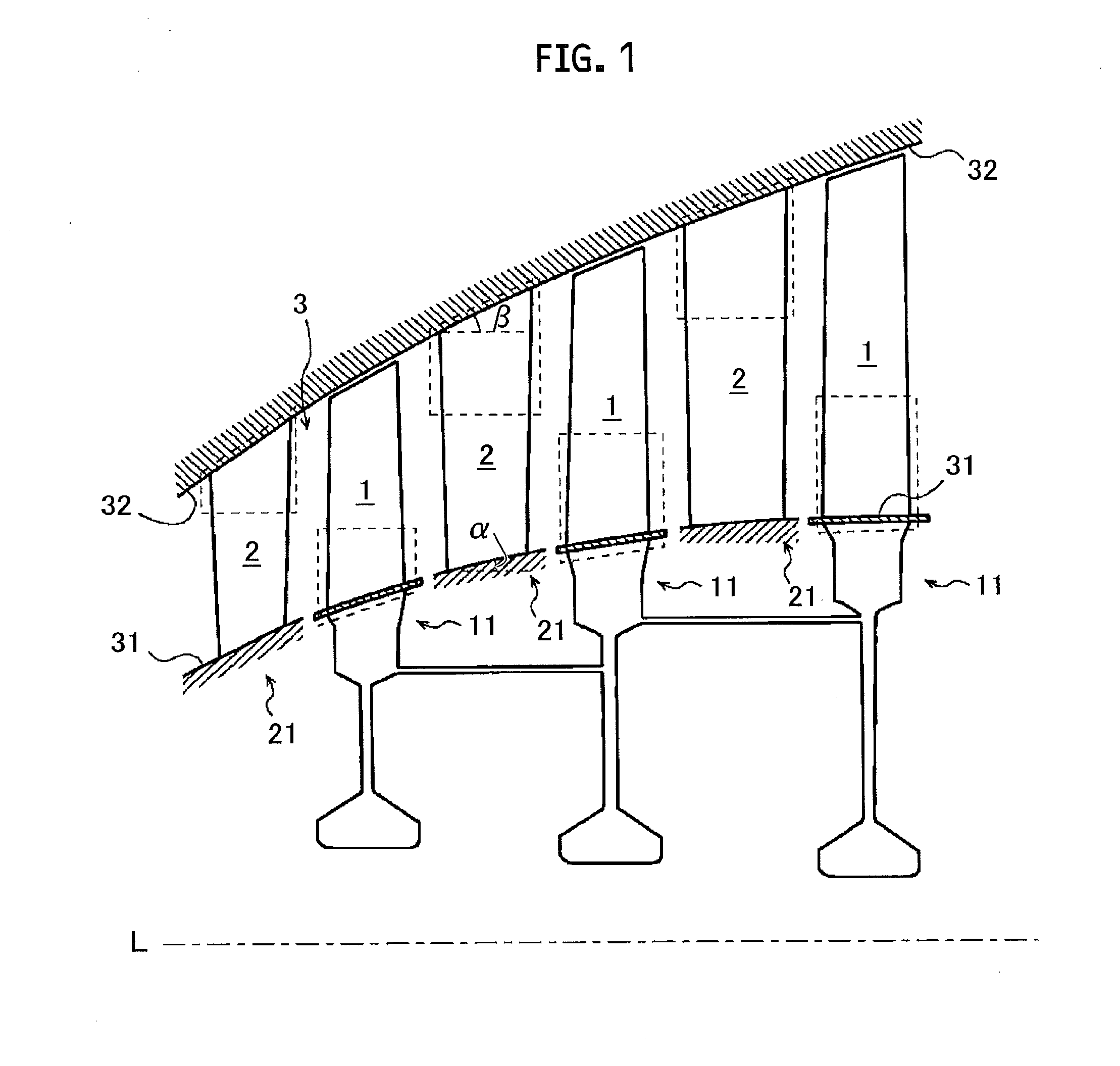
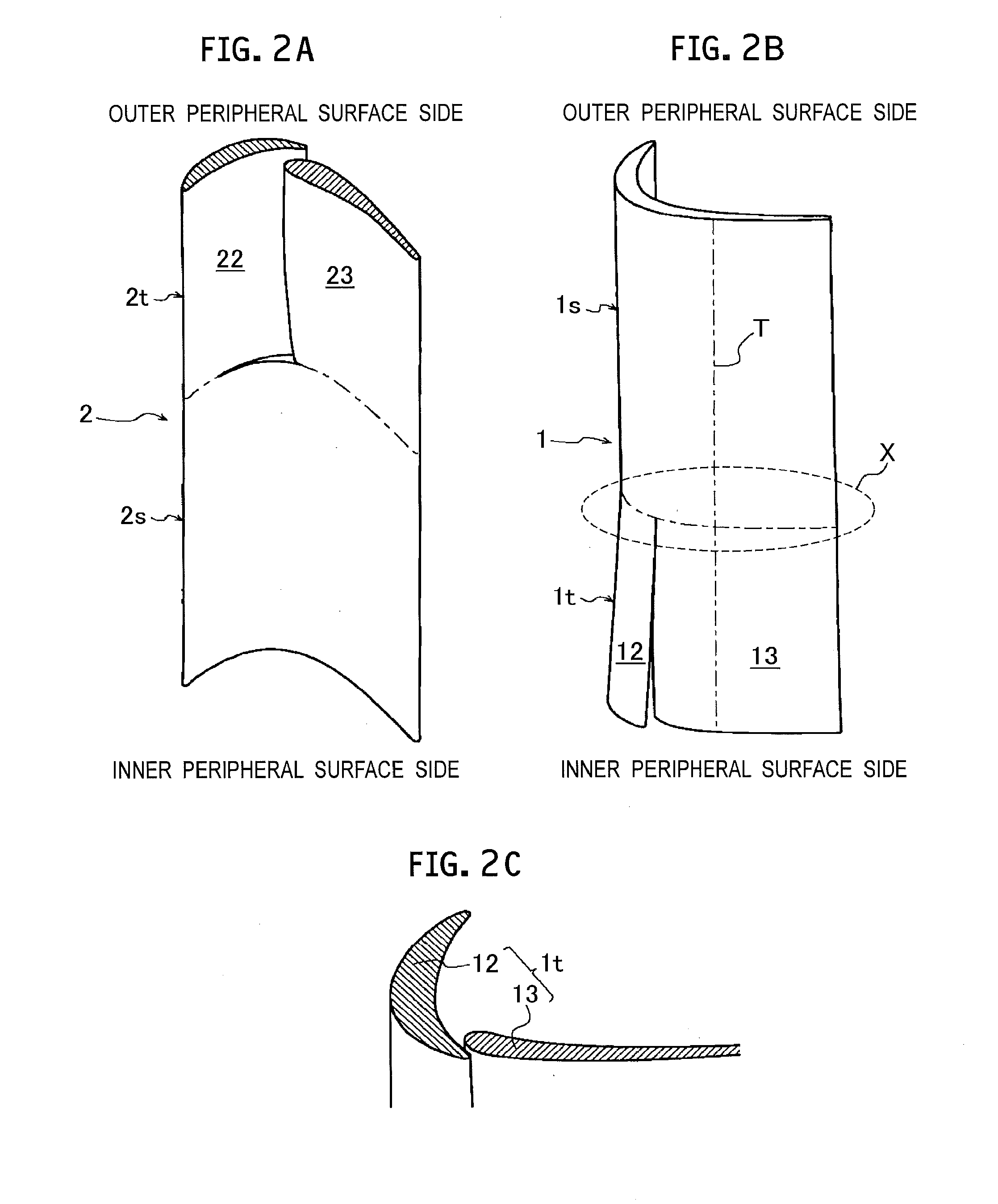
[0027]As shown in FIG. 1, a gas turbine engine according to the embodiment has: a rotor 11 including a plurality of rotor vanes 1; and a stator 21 including a plurality of stator vanes 2. A vane structure of an axial flow turbomachine, which will be described later, is applied to these rotor vanes 1 and stator vanes 2. The gas turbine engine is, for e...


PUM


Abstract

A vane structure for an axial flow turbomachine that has: a single-vane section of a one-vane structure formed in a part in a vane radial direction; and a tandem-vane section which is formed in a remaining part in the vane radial direction continuously with the single-vane section, and which includes a front vane and a rear vane arranged forward and backward with respect to an airflow that flows through a flow path, respectively.

Description

CROSS REFERENCE TO RELATED APPLICATIONS[0001]This application is a continuation application of International Application No. PCT / JP2014 / 077151, filed on Oct. 10, 2014, which claims priority to Japanese Patent Application No. 2013-236476, filed on Nov. 15, 2013, the entire contents of which are incorporated by reference herein.BACKGROUND[0002]1. Technical Field[0003]The present disclosure relates to a vane structure for an axial flow turbomachine and a gas turbine engine which are obtained by the improvement of efficiency.[0004]2. Description of the Related Art[0005]An axial flow turbomachine, such as an axial flow compressor and an axial flow turbine, includes a rotor having a plurality of rotor vanes and a stator having a plurality of stator vanes, the rotor and the stator being arranged in a plurality of stages in an axial direction. The axial flow turbomachine is used in, for example, a gas turbine engine for aircrafts in many cases. In the rotor vane or the stator vane of the ax...

Claims


Application Information

Patent Timeline
IPC IPC(8): F01D5/14F01D9/04
CPCF01D5/146F05D2250/711F05D2220/32F01D9/041Y02T50/60
Inventor TANIMITSU, HARUYUKI
Owner IHI CORP
Why Eureka
Try Eureka