
Cryocooler and cryocooler operation method

Active Publication Date: 2016-06-23
SUMITOMO HEAVY IND LTD
View PDF1 Cites 4 Cited by
  • Summary
  • Abstract
  • Description
  • Claims
  • Application Information

AI Technical Summary

Benefits of technology

The patent aims to develop a technology that minimizes the temperature reached by a cryocooler.

Problems solved by technology

With displacer-type cryocoolers, while the displacer in the cylinder interior is reciprocated, helium inside the expander is made to expand, giving rise to coldness.

Method used


Image

  • Cryocooler and cryocooler operation method
  • Cryocooler and cryocooler operation method
  • Cryocooler and cryocooler operation method

Examples


Embodiment Construction

[0013]It is desirable to provide a technology which decreases a reached temperature of coldness generated by a cryocooler.

[0014]According to certain embodiments of the present invention, it is possible to provide a technology which decreases a reached temperature of coldness generated by a cryocooler.

[0015]An embodiment of the present invention will be described with reference to the drawings.

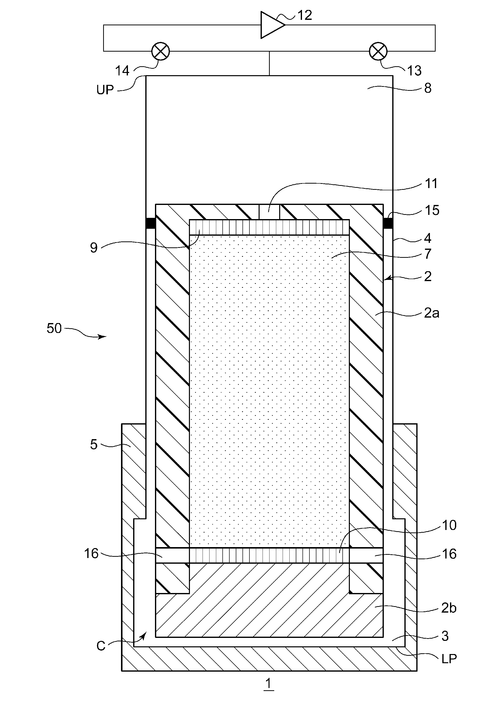
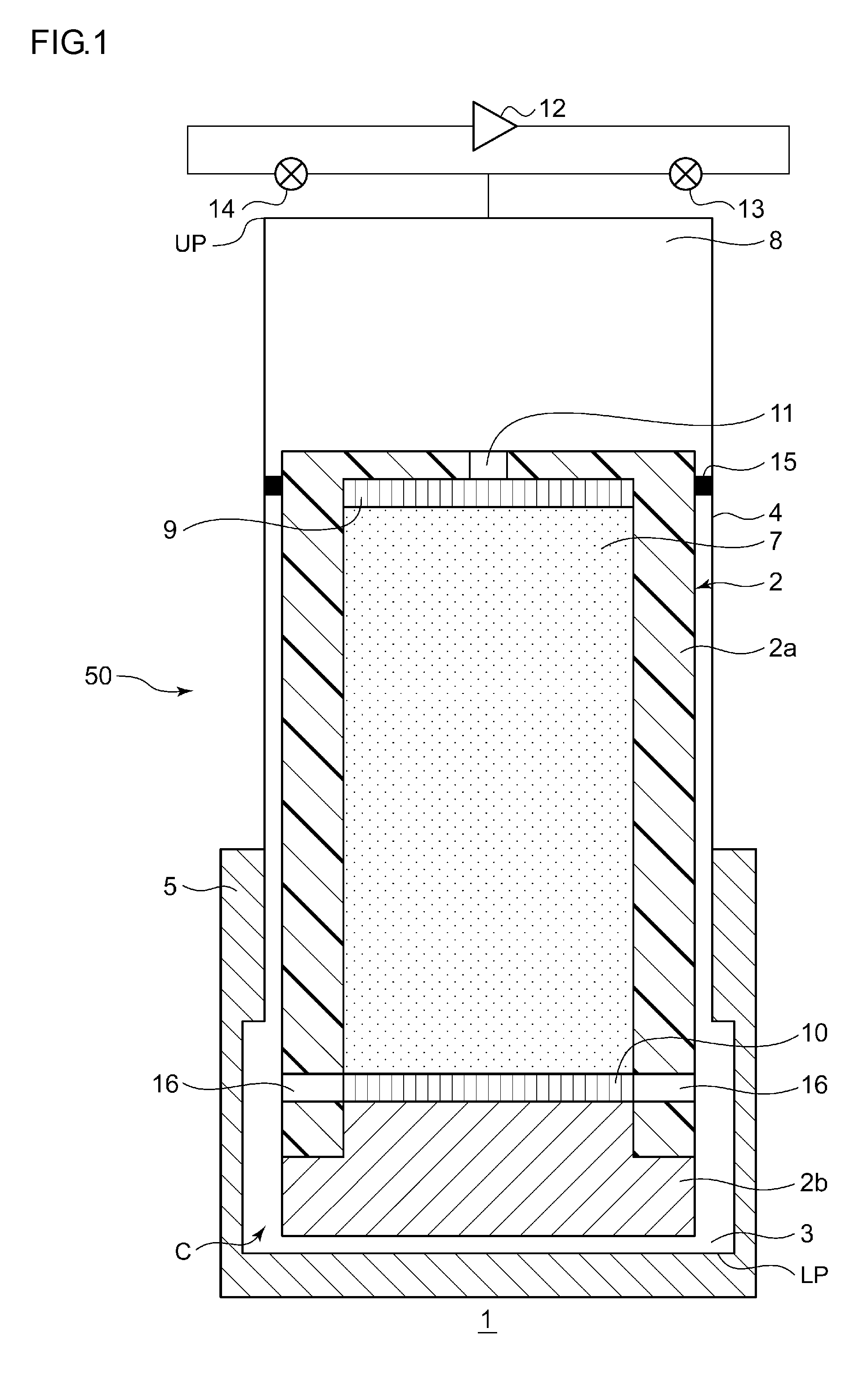
[0016]FIG. 1 is a schematic diagram showing a cryocooler 1 according to an embodiment of the present invention. The cryocooler 1 according to the embodiment is a Gifford McMahon type freezer which uses helium of helium-4 (4He) as a refrigerant gas. The cryocooler 1 includes a cylinder 4 which forms an expansion space 3 expanding high-pressure helium between a displacer 2 and the cylinder 4, and a tubular bottomed cooling stage 5 which is adjacent to the expansion space 3 and is positioned so as to enclose the expansion 3. The cooling stage 5 functions as a heat exchanger which performs heat exc...


PUM


Abstract

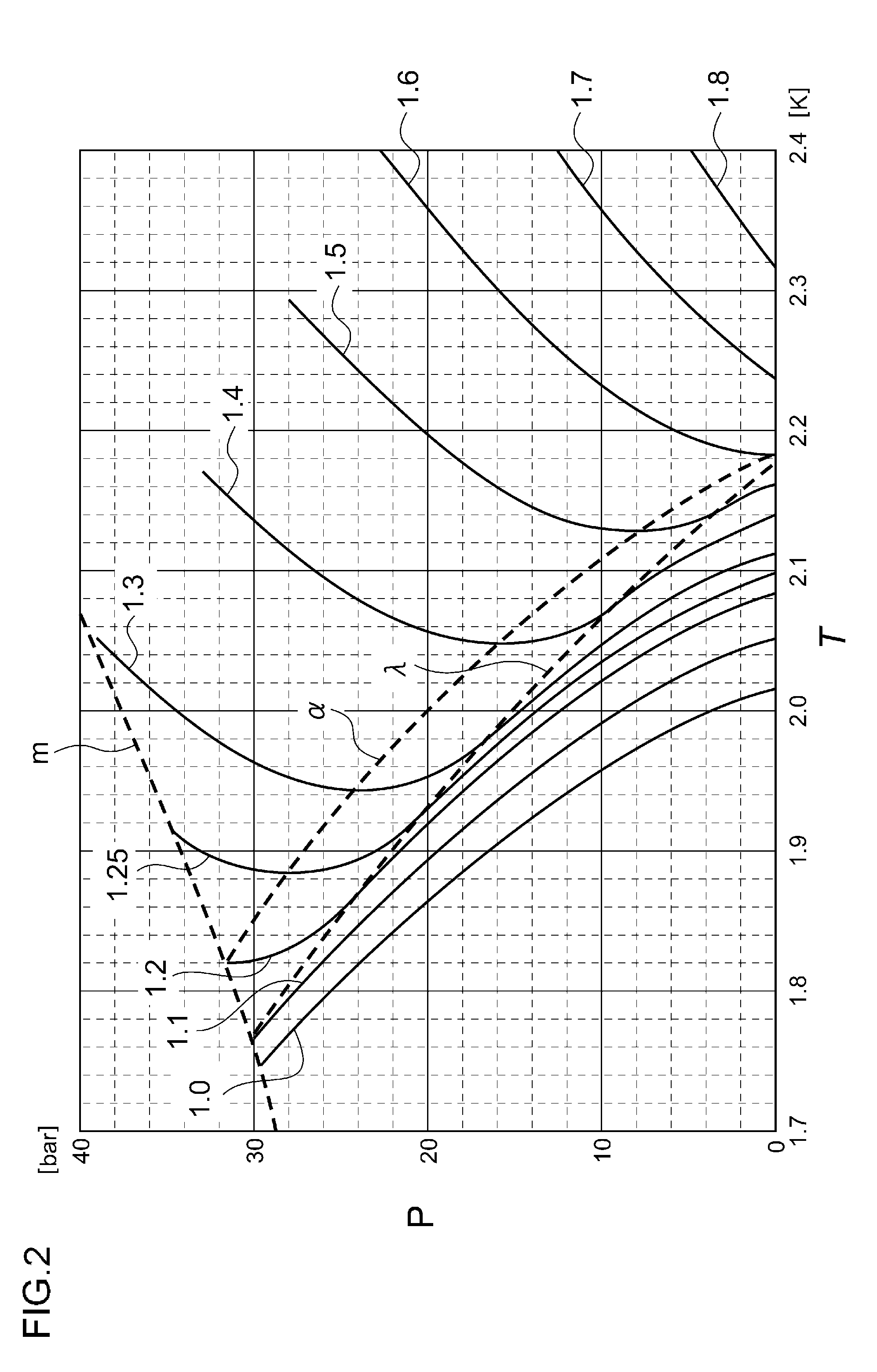
In a cryocooler for developing coldness of 4 K or lower by expanding helium, an expander expands high-pressure helium. A compressor compresses low-pressure helium returned from the expander, to generate high-pressure helium, and supplies the high-pressure helium to the expander. When helium temperature in the expander is 2.17 K or lower, the pressure of the low-pressure helium is equal to or higher than pressure given by a curve, in a helium state diagram in which the horizontal axis is temperature and the vertical axis is pressure, along which helium's volumetric thermal expansion coefficient is 0.

Description

RELATED APPLICATIONS[0001]Priority is claimed to Japanese Patent Application Nos. 2014-259040 and 2015-146032, filed Dec. 22, 2014 and Jul. 23, 2015, the entire content of each of which is incorporated herein by reference.BACKGROUND[0002]1. Technical Field[0003]Certain embodiments of the present invention relate to cryocoolers and cryocooler operation methods that give rise to coldness by expanding high-pressure helium supplied from a compression device.[0004]2. Description of Related Art[0005]Examples of prior-disclosed cryocoolers include displacer-type cryocoolers furnished with an expander configured to movably accommodate a displacer in the interior of a cylinder. With displacer-type cryocoolers, while the displacer in the cylinder interior is reciprocated, helium inside the expander is made to expand, giving rise to coldness. The helium chilling that occurs in the expander builds up in a regenerator and meanwhile is transmitted to a cooling stage, which, reaching a desired cry...

Claims


Application Information

Patent Timeline
IPC IPC(8): F25B9/14
CPCF25B9/14F25B9/06F25B2309/14F25B9/12
Inventor DE WAELE, A.T.A.MXU, MINGYAOBAO, QIAN
Owner SUMITOMO HEAVY IND LTD
Learn More