

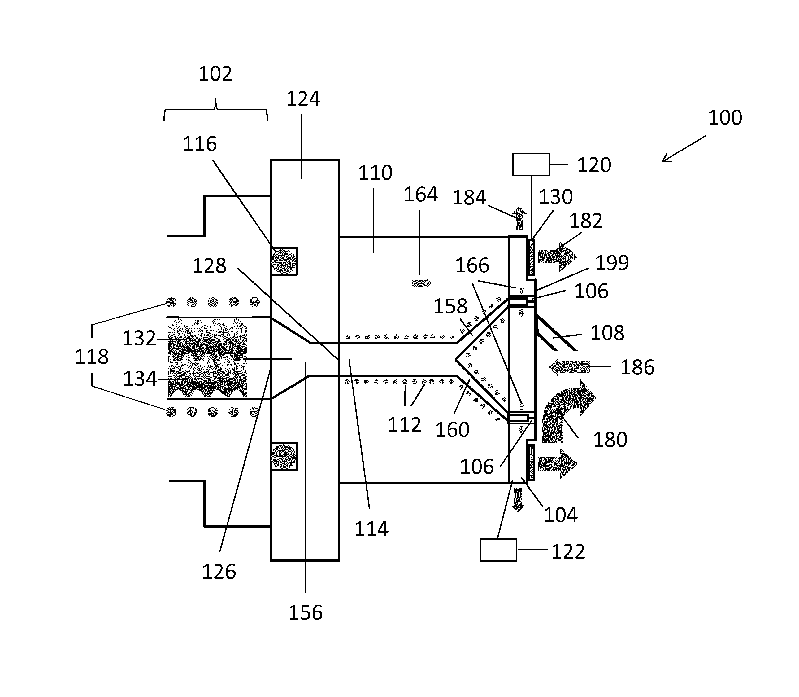
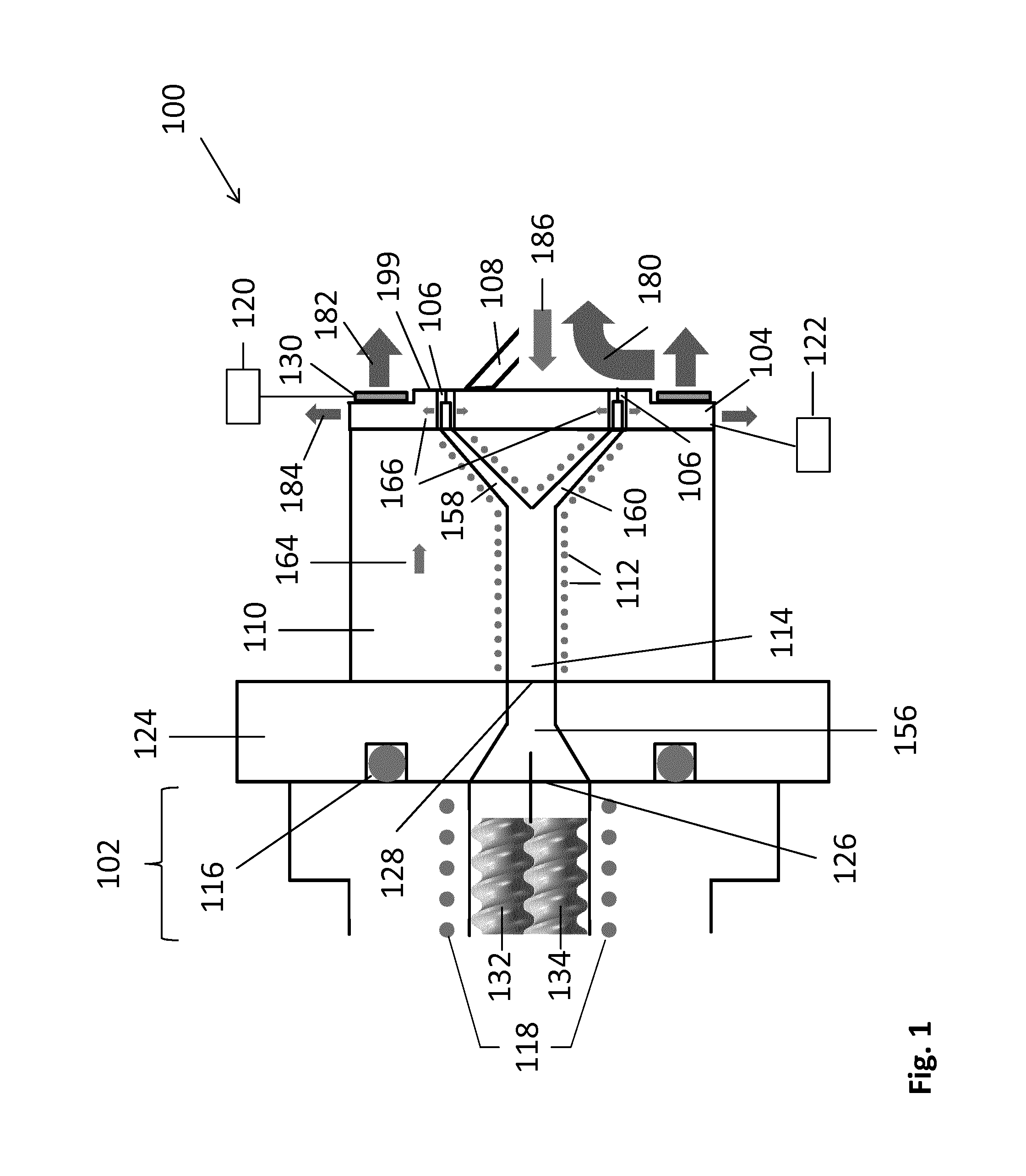
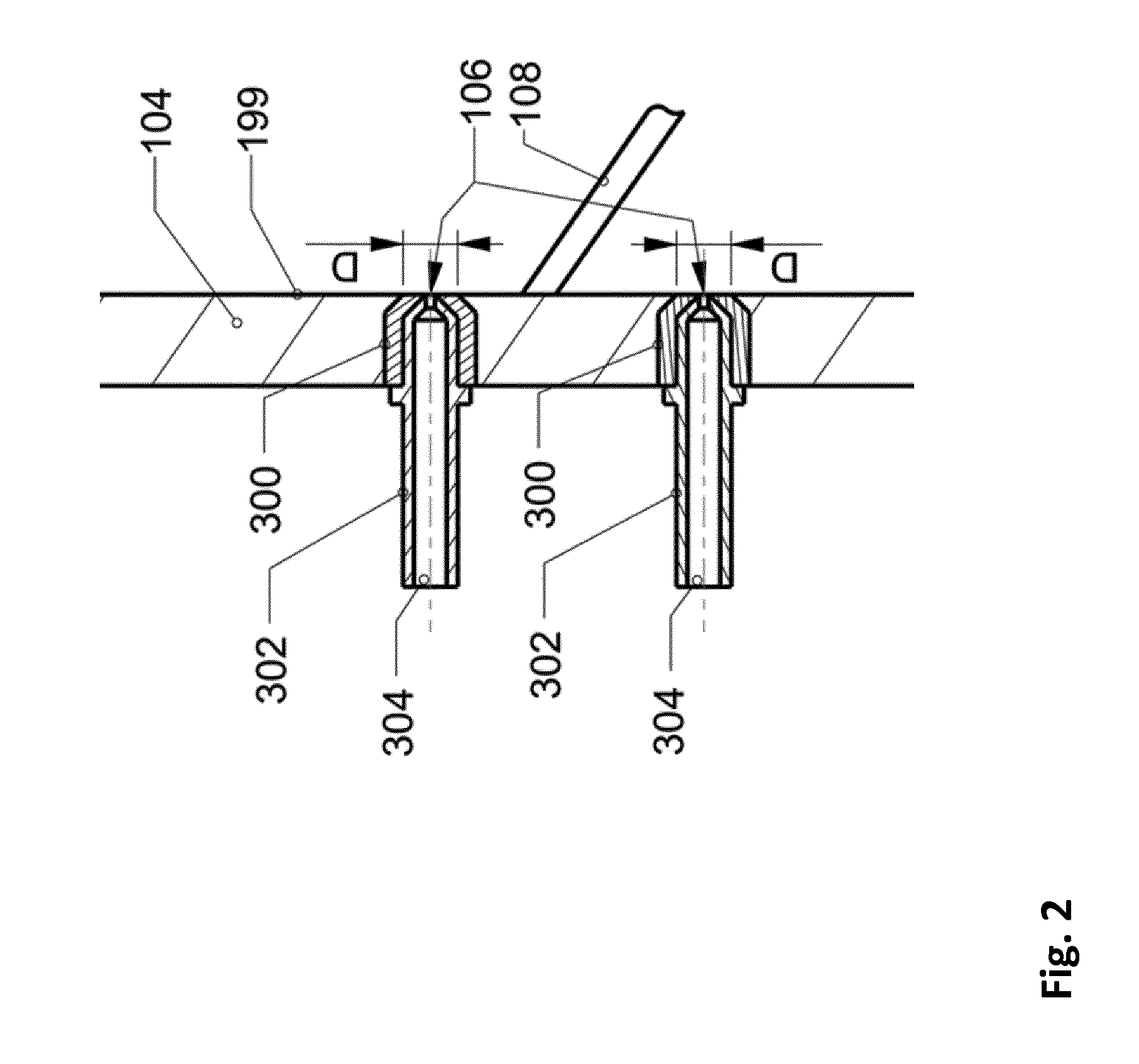
Hot viscous raw material leaving a cooler perforated body cooling a cutter
a perforated body and hot viscous technology, applied in the field of manufacturing particles, can solve the problems of low surface temperature of the perforated body, the cutter and the extruded material, and the commercially available system is only applicable to a very limited extent, so as to prevent undesired adhesion of raw materials, prevent undesired flow of material and/or heat, and achieve the effect of safe operation
- Summary
- Abstract
- Description
- Claims
- Application Information
AI Technical Summary
Benefits of technology
Problems solved by technology
Method used
Image

Examples
Embodiment Construction
[0068]Before specific exemplary embodiments of the invention will be described referring to the drawings, some basic considerations of the present inventors will be summarized based on which exemplary embodiments of the invention have been developed.
[0069]Sticky substances such as molten polymers tend to wet surfaces in the liquid state and form adhesion forces with regard to a contact area as a consequence thereof. The amount of wetting depends on the contact temperature. In the case of pelletizing this is the temperature between cutter and working surface with the extrudate. Due to the heat transport a contact temperature will be present at the contact surface. It depends on the thermal properties and the core temperature of the materials. When the contact temperature is above the solidifying temperature of the extrudate, the material at the contact surface can flow into voids in the rough surface and can therefore form adhesion forces. The time required for the flow into the micr...
PUM
| Property | Measurement | Unit |
|---|---|---|
| Fraction | aaaaa | aaaaa |
| Fraction | aaaaa | aaaaa |
| Fraction | aaaaa | aaaaa |
Abstract
Description
Claims
Application Information