
Target formed of Sintering-Resistant Material of High-Melting Point Metal Alloy, High-Melting Point Metal Silicide, High-Melting Point Metal Carbide, High-Melting Point Metal Nitride, or High-Melting Point Metal Boride, Process for Producing the Target, Assembly of the Sputtering Target-Backing Plate, and Process for Producing the Same

a technology of sintering resistance and high-melting point metal, which is applied in the direction of metallic material coating process, non-electric welding apparatus, diaphragm, etc., can solve the problems of target cracking, difficult bonding processing, and difficult machining, so as to achieve the effect of superior ability, inhibit crack generation, and high power sputtering

Active Publication Date: 2009-09-17
JX NIPPON MINING& METALS CORP
View PDF21 Cites 21 Cited by
  • Summary
  • Abstract
  • Description
  • Claims
  • Application Information

AI Technical Summary

Benefits of technology

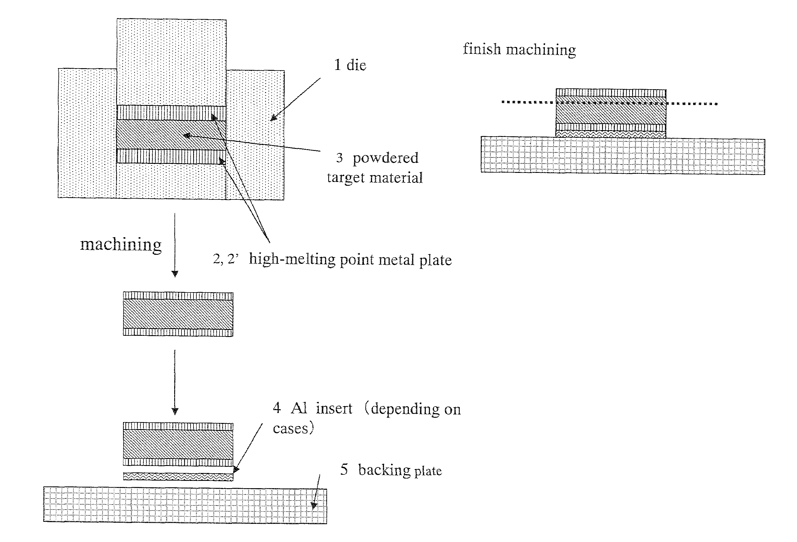
[0021]In light of the problematic points encountered by the conventional technology as described above, the present invention provides a method of producing, with relative ease, a target formed of a sintering-resistant material of high-melting point metal alloy, high-melting point metal silicide, high-melting point metal carbide, high-melting point metal nitride or high-melting point metal boride, which has poor machinability, as well as a high-melting point metal alloy or high-melting point metal ceramic sintered compact and its production method of effectively inhibiting the generation of cracks during the target production and high power sputtering, inhibiting the reaction of the target raw material with the die during hot pressing, and also reducing the warpage of the target.
[0026]The present invention yields a superior effect of being able to produce, with relative ease, a high-melting point metal alloy or high-melting point metal ceramic target. High power sputtering is enabled since it is possible to effectively inhibit the generation of cracks during the target production and sputtering. The present invention also yields significant effects of being able to inhibit the reaction of the target raw material with the die, reduce the warpage of the target during the target production, and perform ion sputtering in which the sputtered particles are ionized.

Problems solved by technology

However, there is a problem in that machining is difficult since the material is hard and brittle.
When placing a target formed of high-melting point metal alloy or high-melting point metal ceramic on a sputtering device, it is necessary to bond such target to a backing plate, but there is an additional problem in that this processing of bonding is in itself difficult.
Although there are demands for performing ionization during the sputtering and performing such sputtering with high power, there is a problem in that, with a target that is solder-bonded using a brazing filler material or the like, the target will crack due to the melting or the like of the brazing filler material.
Even if this technology is applied to the production of a high-melting point metal alloy or high-melting point metal ceramic target and the target is prepared in a plate shape in advance, there is a problem in that the preparation for bonding the target with the backing plate cannot be made since it is not possible to perform crude processing to the bonding interface of the target.
Accordingly, there is a problem in that this technology cannot be applied to the production of a high-melting point metal alloy or high-melting point metal ceramic target.
Nevertheless, with a target that is a high-melting point material and which is to be sputtered at high power, the bonding method using a brazing filler material having a low melting point cannot be adopted since it may cause an accident where such brazing filler material falls off during the sputtering.
This technology also entails the problems encountered in Patent Documents 1 and 2 described above, and cannot be applied to the production of a high-melting point metal alloy or high-melting point metal ceramic target.
This technology is for use as an X-ray tube target material and relates to a special production method, but since it does not in any solve the problem regarding the bonding of the target to the backing plate, it cannot be applied to the production of high-melting point metal alloy or high-melting point metal.
This technology is inefficient since the use of a vacuumed can is troublesome.
Moreover, although it is desirable to use a copper or copper alloy backing plate from the perspective of cooling efficiency, if the difference in the melting point between the target and the backing plate is significant as in this case, there is a problem in that the method cannot be applied since the bonding will be difficult.
Nevertheless, in this case, it is a problem in that this is possible only when the target material itself has workability, and cannot be applied to the production of a high-melting point metal alloy or high-melting point metal ceramic target.
This technology does not overcome the problem of bonding highly brittle sintering materials.
From a comprehensive standpoint, it is extremely difficult to product a target formed of high-melting point metal alloy or high-melting point metal ceramic with the conventional technology, and it was not possible to overcome the problem of target cracking during the production or sputtering.

Method used


Image

  • Target formed of Sintering-Resistant Material of High-Melting Point Metal Alloy, High-Melting Point Metal Silicide, High-Melting Point Metal Carbide, High-Melting Point Metal Nitride, or High-Melting Point Metal Boride, Process for Producing the Target, Assembly of the Sputtering Target-Backing Plate, and Process for Producing the Same
  • Target formed of Sintering-Resistant Material of High-Melting Point Metal Alloy, High-Melting Point Metal Silicide, High-Melting Point Metal Carbide, High-Melting Point Metal Nitride, or High-Melting Point Metal Boride, Process for Producing the Target, Assembly of the Sputtering Target-Backing Plate, and Process for Producing the Same

Examples


examples

[0059]The present invention is now explained in detail with reference to the Examples. These Examples are merely illustrative, and the present invention shall in no way be limited thereby. In other words, various modifications and other embodiments based on the technical spirit claimed in the claims shall be included in the present invention as a matter of course.

(Example 1-1) to (Example 1-30)

[0060]As the high-melting point metal, plates formed of tantalum, niobium, vanadium, titanium or molybdenum respectively having a thickness of 1 mmt, 2 mmt, 4 mmt, 6 mmt, 8 mmt, and 10 mmt were used, the high-melting point metal plate was placed in a graphite die, and, as the high-melting point metal alloy to become the raw material of the target, tungsten carbide powder, tantalum carbide powder, zirconium boride powder, tantalum silicide powder, tungsten silicide powder, titanium nitride powder, and tantalum nitride powder were respectively filled on the high-melting point metal plate. These ...


PUM

PropertyMeasurementUnit
thicknessaaaaaaaaaa
temperatureaaaaaaaaaa
thicknessaaaaaaaaaa

Abstract

Provided is a target formed of a sintering-resistant material of high-melting point metal alloy, high-melting point metal silicide, high-melting point metal carbide, high-melting point metal nitride or high-melting point metal boride comprising a structure in which a target material formed of a sintering-resistant material of high-melting point metal alloy, high-melting point metal silicide, high-melting point metal carbide, high-melting point metal nitride or high-melting point metal boride and a high-melting point metal plate other than the target material are bonded. Additionally provided is a production method of such a target capable of producing, with relative ease, a target formed of a sintering-resistant material of high-melting point metal alloy, high-melting point metal silicide, high-melting point metal carbide, high-melting point metal nitride or high-melting point metal boride, which has poor machinability, can relatively easily produced. Further the generation of cracks during the target production and high power sputtering, and the reaction of the target raw material with the die during hot pressing can be inhibited effectively, and the warpage of the target can be reduced.

Description

TECHNICAL FIELD[0001]The present invention relates to a method of producing, with relative ease, a target formed of a sintering-resistant material of high-melting point metal alloy, high-melting point metal silicide, high-melting point metal carbide, high-melting point metal nitride or high-melting point metal boride, which has poor machinability. Specifically, the present invention relates to a target formed of a sintering-resistant material of high-melting point metal alloy, high-melting point metal silicide, high-melting point metal carbide, high-melting point metal nitride or high-melting point metal boride and its production method of inhibiting the generation of cracks during the target production and high power sputtering effectively. The present invention also relates to a sputtering target-backing plate assembly and its production method.[0002]The term “high-melting point metal” as referred to herein is 4A, 5A, 6A, 7A, and 8 group metal having a melting point of approximate...

Claims


Application Information

Patent Timeline
Patent Type & Authority Applications(United States)
IPC IPC(8): C23C14/34B22F7/04
CPCC04B37/026C04B2237/121C04B2237/36C04B2237/403C23C14/3414C04B2237/708C23C14/0635C23C14/0682C04B2237/706H01J37/3426B22F7/08B23K20/02C23C14/34H01L21/02365B22F2003/247B22F2007/045B22F2302/05B22F2302/10B22F2302/20B22F2302/45B22F2303/01B22F2998/10B22F3/162B22F3/24B22F7/04C23C14/0641C23C14/067C23C14/14
Inventor YAMAKOSHI, YASUHIRO
Owner JX NIPPON MINING& METALS CORP
Learn More