

Rotating electrical machine apparatus
- Summary
- Abstract
- Description
- Claims
- Application Information
AI Technical Summary
Benefits of technology
Problems solved by technology
Method used
Image

Examples
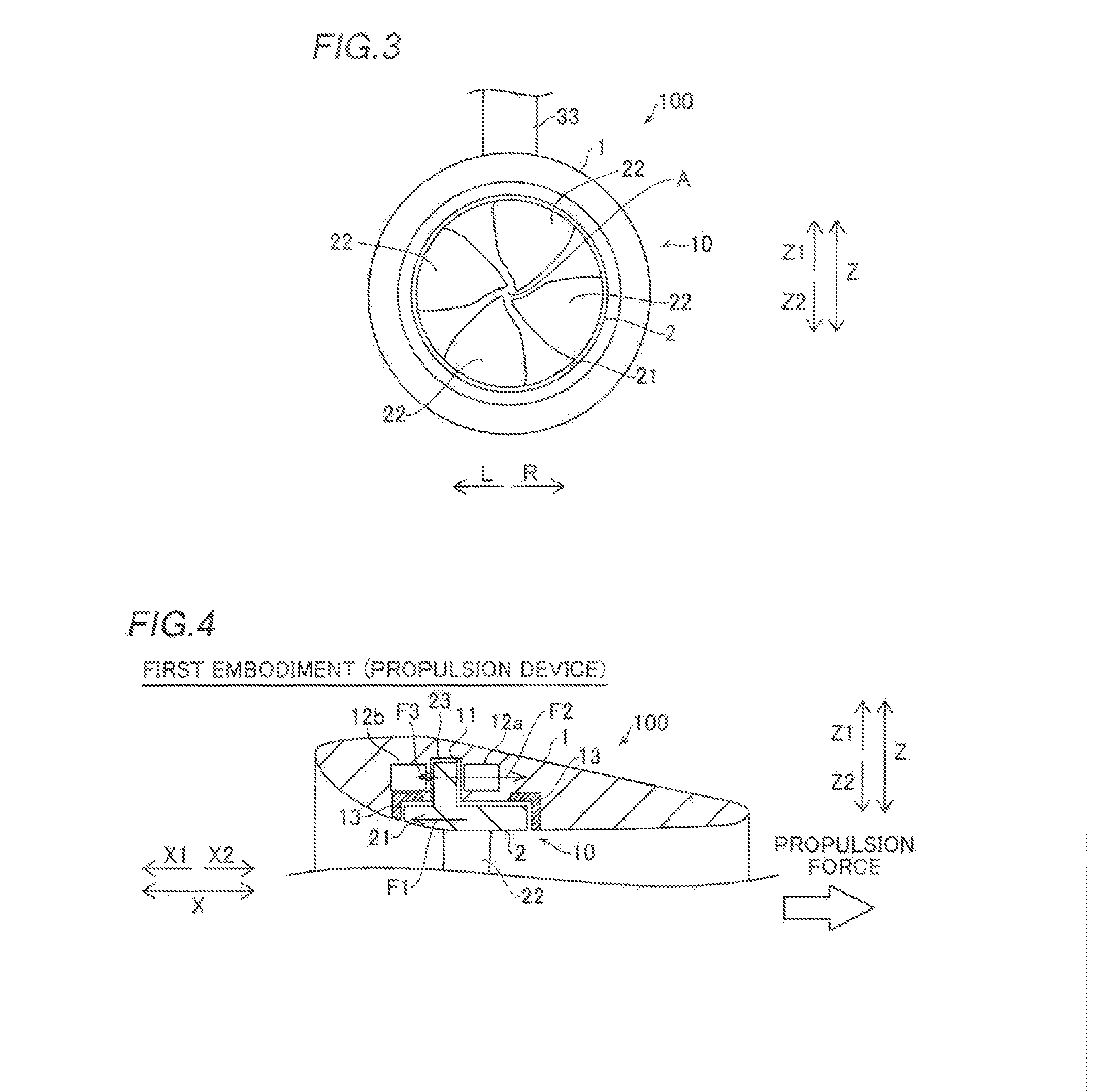
first embodiment
Modification of First Embodiment
First Modification
[0085]A modification (first modification) of the first embodiment of the present invention is now described with reference to FIG. 6. In this first modification, a rotating electrical machine apparatus is employed as a generator.
[0086]As shown in FIG. 6, a rotating electrical machine apparatus 100a according to the first modification includes a generator that generates electric power by rotating blades 22 according to flow of an external fluid. In other words, in the rotating electrical machine apparatus 100a, a rotor portion 23 is rotated by rotation of the blades 22, and a magnetic field is changed. A switching element of a converter is switched such that electric currents flow in coils of stator portions 12a and 12b by the change of the magnetic field, and electric power is generated.
[0087]When water flows from a direction X1 toward a direction X2, the force of the water flow is converted into the rotation force of a rim 2, and a ...
second embodiment
Modification of Second Embodiment
Second Modification
[0098]A modification (second modification) of the second embodiment of the present invention is now described with reference to FIG. 8. In this second modification, a rotating electrical machine apparatus is employed as a generator.
[0099]As shown in FIG. 8, a rotating electrical machine apparatus 300a according to the second modification includes a generator that generates electric power by rotating blades 22 according to flow of an external fluid. In other words, in the rotating electrical machine apparatus 300a, a rotor portion 23 is rotated by rotation of the blades 22, and a magnetic field is changed. A stator portion 14a is arranged in a direction X1 relative to the rotor portion 23. A switching element of a converter is switched such that an electric current flows in a coil of the stator portion 14a by the change of the magnetic field, and electric power is generated.
[0100]When water flows from the direction X1 toward a direc...
third embodiment
Modification of Third Embodiment
Third Modification
[0112]A modification (third modification) of the third embodiment of the present invention is now described with reference to FIG. 10. In this third modification, a rotating electrical machine apparatus is employed as a generator.
[0113]As shown in FIG. 10, a rotating electrical machine apparatus 400a according to the third modification includes a generator that generates electric power by rotating blades 22 according to flow of an external fluid. In other words, in the rotating electrical machine apparatus 400a, a rotor portion 23 is rotated by rotation of the blades 22, and a magnetic field is changed. An electric current flows in a coil of a stator portion 15a by the change of the magnetic field, and electric power is generated.
[0114]When water flows from a direction X1 toward a direction X2, the force of the water flow is converted into the rotation force of a rim 2, and a force F14 acts in the direction X2. A suction force F15 is...
PUM
 Abstract
Description
Claims
Application Information