
Method of and system for remote diagnostics of an operational system

Active Publication Date: 2016-06-30
BAKER HUGHES INC
View PDF4 Cites 57 Cited by
  • Summary
  • Abstract
  • Description
  • Claims
  • Application Information

AI Technical Summary

Benefits of technology

The patent text describes a method of remotely reducing downtime of an operational system by accessing information from the system and using it to monitor and improve its performance. A diagnostic computer is used to access information from various components of the system, including a prime mover controller, user interface computer, switches, and sensors. This information is then transmitted to an off-site operations center, where it is used to improve system performance, assess communication issues, and troubleshoot equipment. The off-site operations center can also communicate with the operational system to address issues remotely. The method also includes the use of modular system devices, such as cameras and audio communication devices, for real-time live operation-viewing and analysis. The information collected from these devices is recorded and played back for further analysis and reporting. Overall, this method provides quick maintenance and troubleshooting of operational systems while minimizing downtime.

Problems solved by technology

Well construction, and subsequent production therefrom and monitoring thereof, involve expensive, time-consuming operations and personnel having varying degrees of knowledge with respect to certain facets of the operations.
It is not always economically or operationally feasible to provide subject matter experts (“SMEs”) onsite for the entirety of such operations.
Additionally, various types of interrelated information are not available in time-synchronized form and integrated or correlated form for real-time use or for performing analysis.

Method used


Image

  • Method of and system for remote diagnostics of an operational system
  • Method of and system for remote diagnostics of an operational system
  • Method of and system for remote diagnostics of an operational system

Examples


embodiment 1

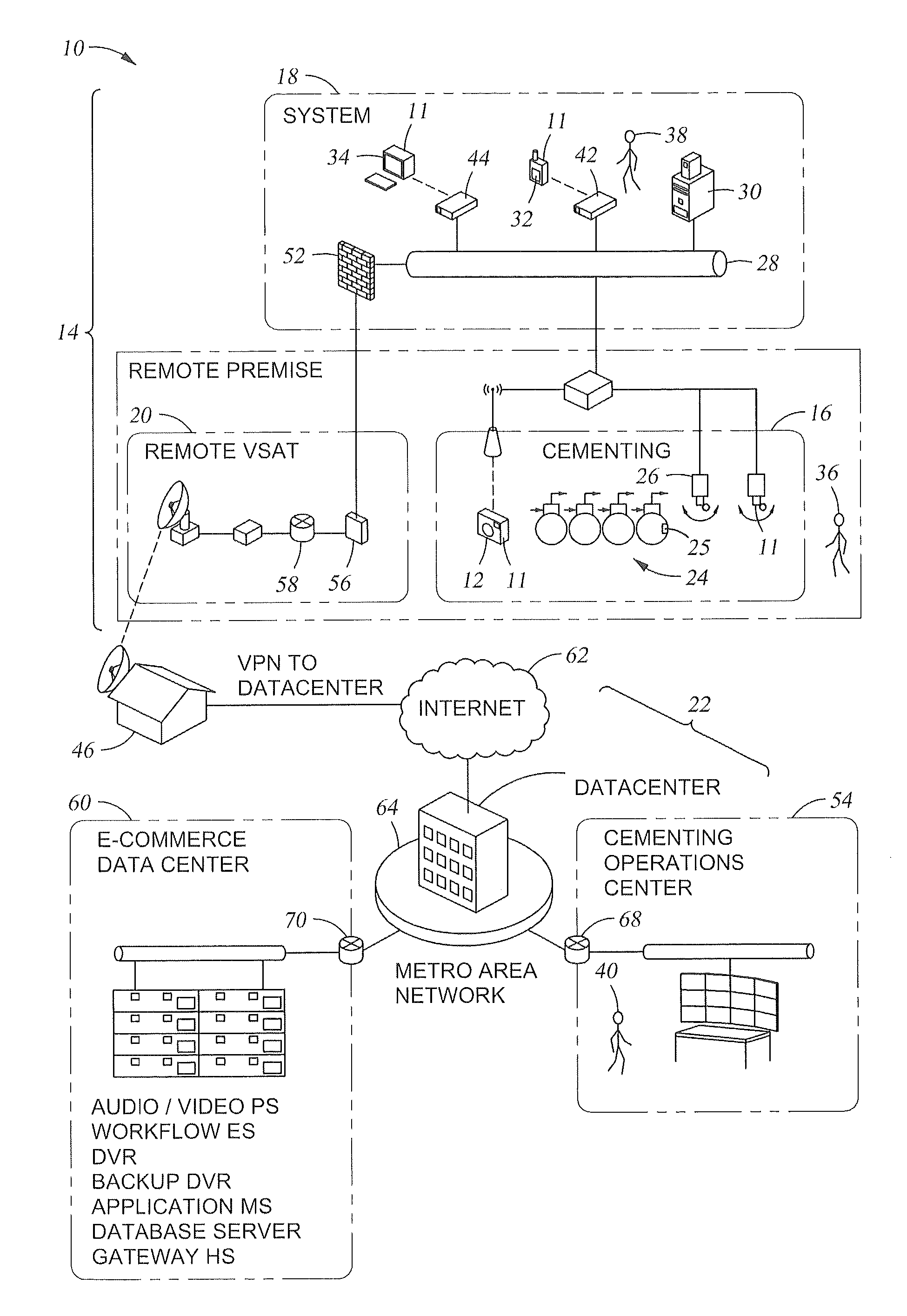
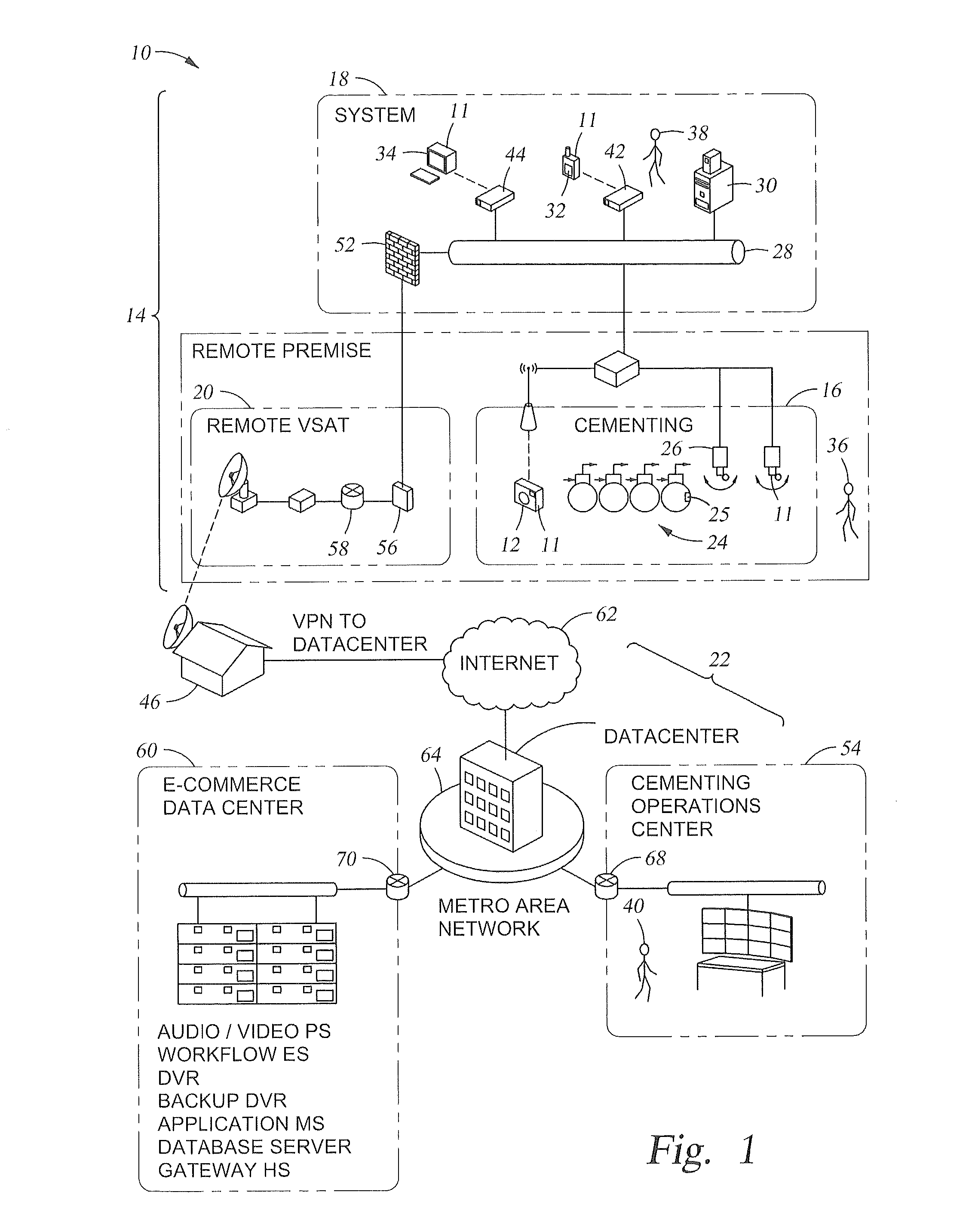
[0091]A method of remotely reducing downtime of an operational system, the method comprising: directly accessing information from the operational system by a diagnostic computer, the information accessed from at least one prime mover controller, a user interface computer, at least one switch, at least one networking connection, and at least one sensor configured to sense and capture a measurable parameter of the operational system; transmitting the information from the diagnostic computer to an off-site operations center; using the information at the off-site operations center to monitor, review or improve status and performance of components within the operational system; using the information at the off-site operations center to assess communication status and connectivity issues of connections between the components of the operational system; and, communicating issues with the operational system from the off-site operations center to the operational system.

embodiment 2

[0092]The method of remotely reducing downtime of embodiment 1, further comprising directly accessing information from two or more separate and locationally distinct operational systems by a diagnostic computer at each operational system and communicating issues with the two or more operational systems from the same off-site operations center.

embodiment 3

[0093]The method of remotely reducing downtime of embodiment 1, wherein directly accessing information from the operational system includes accessing information from a cementing unit.


PUM


Abstract

A method of remotely reducing downtime of an operational system includes directly accessing information from the operational system by a diagnostic computer, the information accessed from at least one prime mover controller, a user interface computer, at least one switch, at least one networking connection, and at least one sensor configured to sense and capture a measurable parameter of the operational system; transmitting the information from the diagnostic computer to an off-site operations center; using the information at the off-site operations center to monitor, review or improve status and performance of components within the operational system; using the information at the off-site operations center to assess communication status and connectivity issues of connections between the components of the operational system; and, communicating issues with the operational system from the off-site operations center to the operational system.

Description

CROSS REFERENCE TO RELATED APPLICATIONS[0001]This application claims the benefit of an earlier filing date from U.S. Provisional Application Ser. No. 62 / 090,059 filed Dec. 10, 2014, the entire disclosure of which is incorporated herein by reference.BACKGROUND[0002]In the drilling and completion industry, the formation of boreholes for the purpose of production or injection of fluid is common. The boreholes are used for exploration or extraction of natural resources such as hydrocarbons—oil and gas, and / or controlled injection of produced fluids (water, CO2, etc.) for disposal, reservoir pressure maintenance or sequestration. Well construction, and subsequent production therefrom and monitoring thereof, involve expensive, time-consuming operations and personnel having varying degrees of knowledge with respect to certain facets of the operations. It is not always economically or operationally feasible to provide subject matter experts (“SMEs”) onsite for the entirety of such operation...

Claims


Application Information

Patent Timeline
IPC IPC(8): E21B41/00
CPCE21B41/0092E21B33/13E21B44/00
Inventor HARKLESS, TOBY J.BURNS, STEPHEN R.BERG, ERIKDAULTON, DANIEL J.KENDRICK, DAVIDJOSE, SUNIL J.
Owner BAKER HUGHES INC
Features
  • Generate Ideas
  • Intellectual Property
  • Life Sciences
  • Materials
  • Tech Scout
  • Unparalleled Data Quality
  • Higher Quality Content
  • 60% Fewer Hallucinations
Learn More