Motion detection device

Active Publication Date: 2016-06-30
NAT SUN YAT SEN UNIV
View PDF3 Cites 79 Cited by
  • Summary
  • Abstract
  • Description
  • Claims
  • Application Information

AI Technical Summary

Benefits of technology

[0007]Accordingly, the disclosure is directed to a motion detection device capable of directly utilizing a signal transmitted by a mobile communication apparatus or a wireless m

Problems solved by technology

For wearing comfort and portable convenience, the portable electronic apparatuses and the wearable electronic apparatuses are developed toward being compact-size, which causes difficulty and inconvenience to the finger touch operations.
However, this system has low resolution for recognizing motions of the target object, which causes difficulty to the application in short-distance gesture detection.
Apparently, the afore

Method used


Image

  • Motion detection device
  • Motion detection device
  • Motion detection device

Examples


Embodiment Construction

[0035]Reference will now be made in detail to the exemplary embodiments of the disclosure, examples of which are illustrated in the accompanying drawings. Wherever possible, the same reference numbers are used in the drawings and the description to refer to the same or like parts.

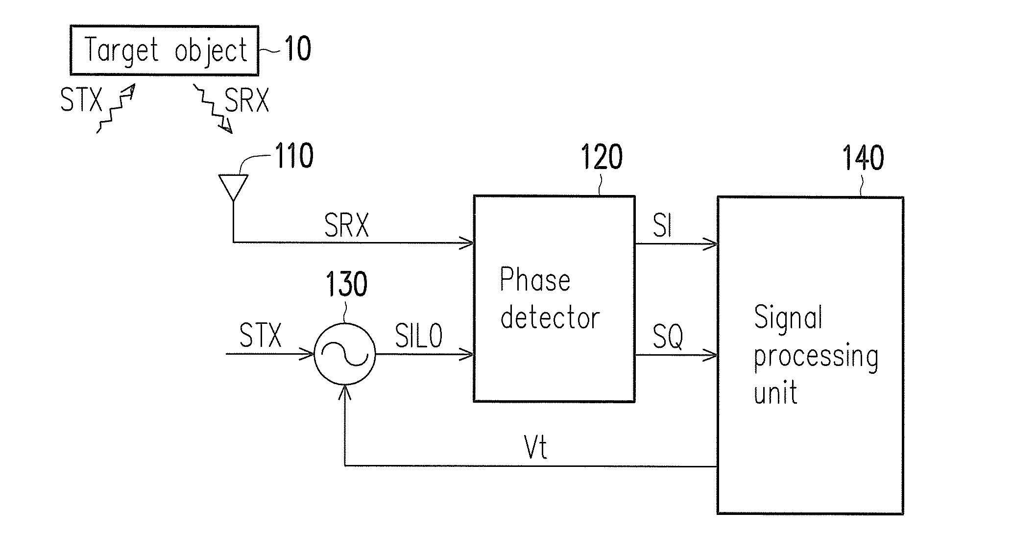
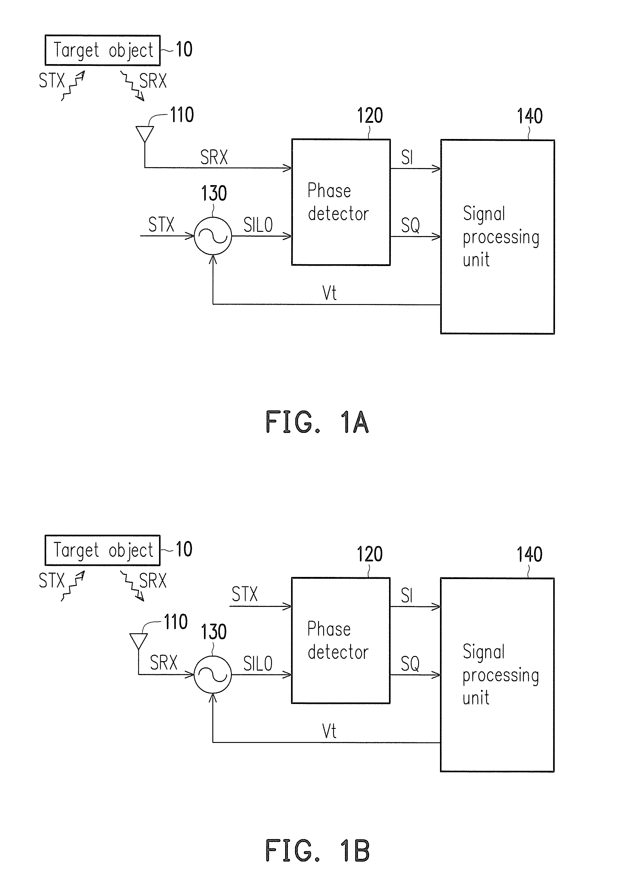
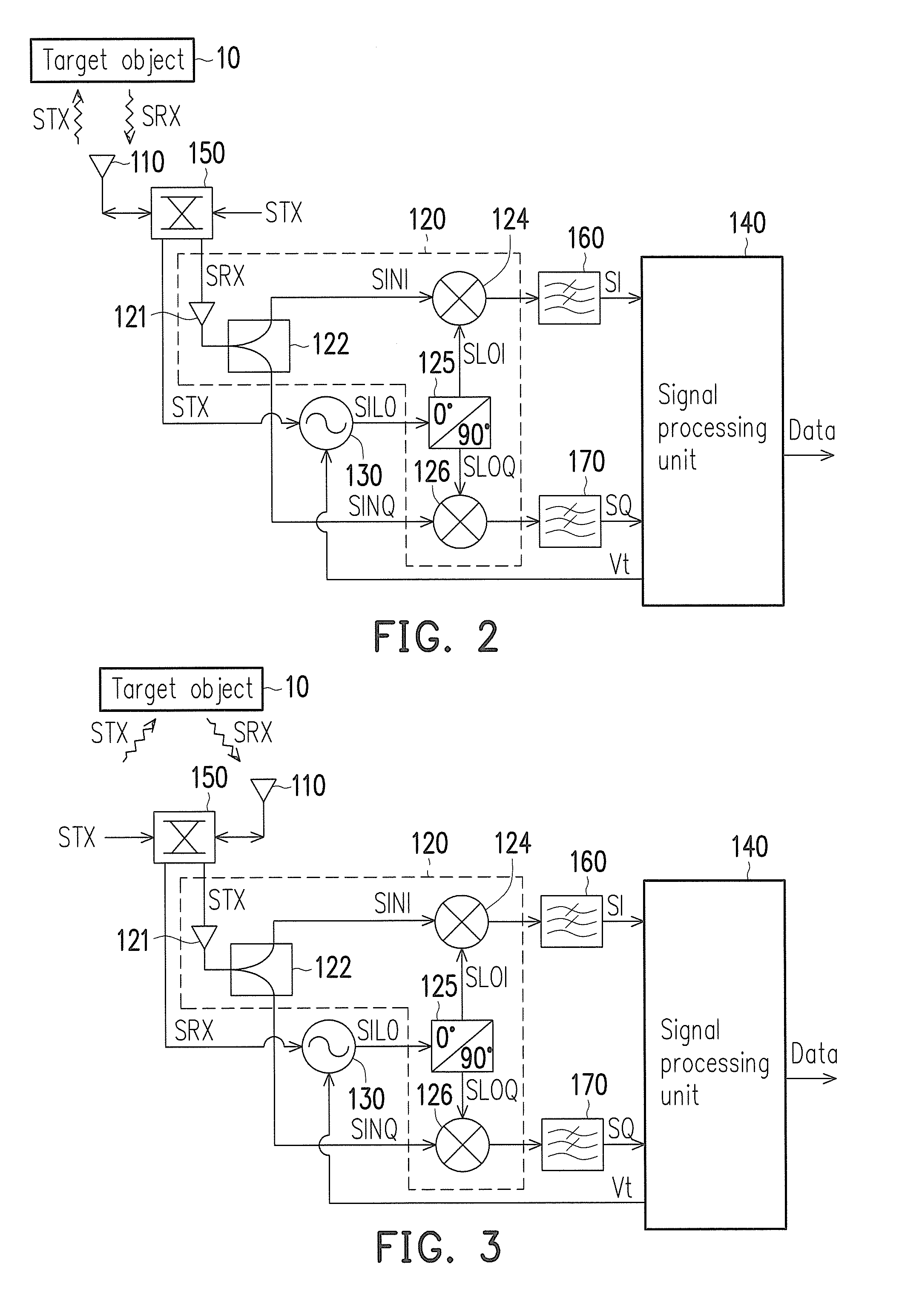
[0036]The disclosure is directed to a motion detection device capable of detecting a gesture and vital signs of a user within a short distance by means of injection-type quadrature receivers and a passive radar detection technique. In the disclosure, the motion detection device does not have to generate and emit a detection signal source by itself, but uses a radio frequency (RF) signal generated by a communication module of a mobile communication apparatus or wireless modulation signal from the surroundings as a detection signal source. Hence, the motion detection device can utilizes a wireless modulation signal (e.g., a Gaussian minimum shift keying (GMSK) signal, a quadrature phase shift keying (QPSK) si...


PUM


Abstract

A motion detection device is provided. The motion detection device includes a first antenna, a voltage-controlled oscillator, a phase detector and a signal processing unit. The first antenna receives a first signal generated by a second signal reflected by a target object, so as to output the first signal to the phase detector or the voltage-controlled oscillator. The voltage-controlled oscillator receives first signal or the second signal and receives a frequency adjustment signal, so as to generate an oscillating signal according to the frequency adjustment signal and the one of the first signal and the second signal. The phase detector receives the oscillating signal and another one of the first signal and the second signal, and generates a first phase output signal and a second phase output signal. The signal processing unit estimates motion parameters of the target object according to the first and the second phase output signal.

Description


Claims


Application Information

Patent Timeline
Owner NAT SUN YAT SEN UNIV
Why Eureka
Try Eureka