
Flow type zinc air fuel cell

a fuel cell and flow-type technology, applied in the field of fuel cells, can solve the problems of limited area in contact with air reaction, inability to adapt to the future society, and huge challenges in energy development, and achieve the effect of increasing the lifespan of the fuel cell

Inactive Publication Date: 2016-06-30
LIAO WEN HUANG
View PDF3 Cites 0 Cited by
  • Summary
  • Abstract
  • Description
  • Claims
  • Application Information

AI Technical Summary

Benefits of technology

The present invention is a zinc air fuel cell that uses a flow type electrode and a driving device to enable continuous reactions involving the transfer of chemical energy. The design allows for the free circulation of the zinc electrode between the discharging and charging pipelines, which eliminates the need for supplementing or replacing the material. The fuel cell is economical, environmentally friendly, and has an increased lifespan. The design also allows for the continuous cyclical oxidation and reduction reaction of the zinc electrode, resulting in the generation of electricity.

Problems solved by technology

A huge energy system built up in the 20th century has been unable to adapt to the future society for the requirements of the efficient, clean, economical and safe energy systems.
As such, energy development is facing a huge challenge.
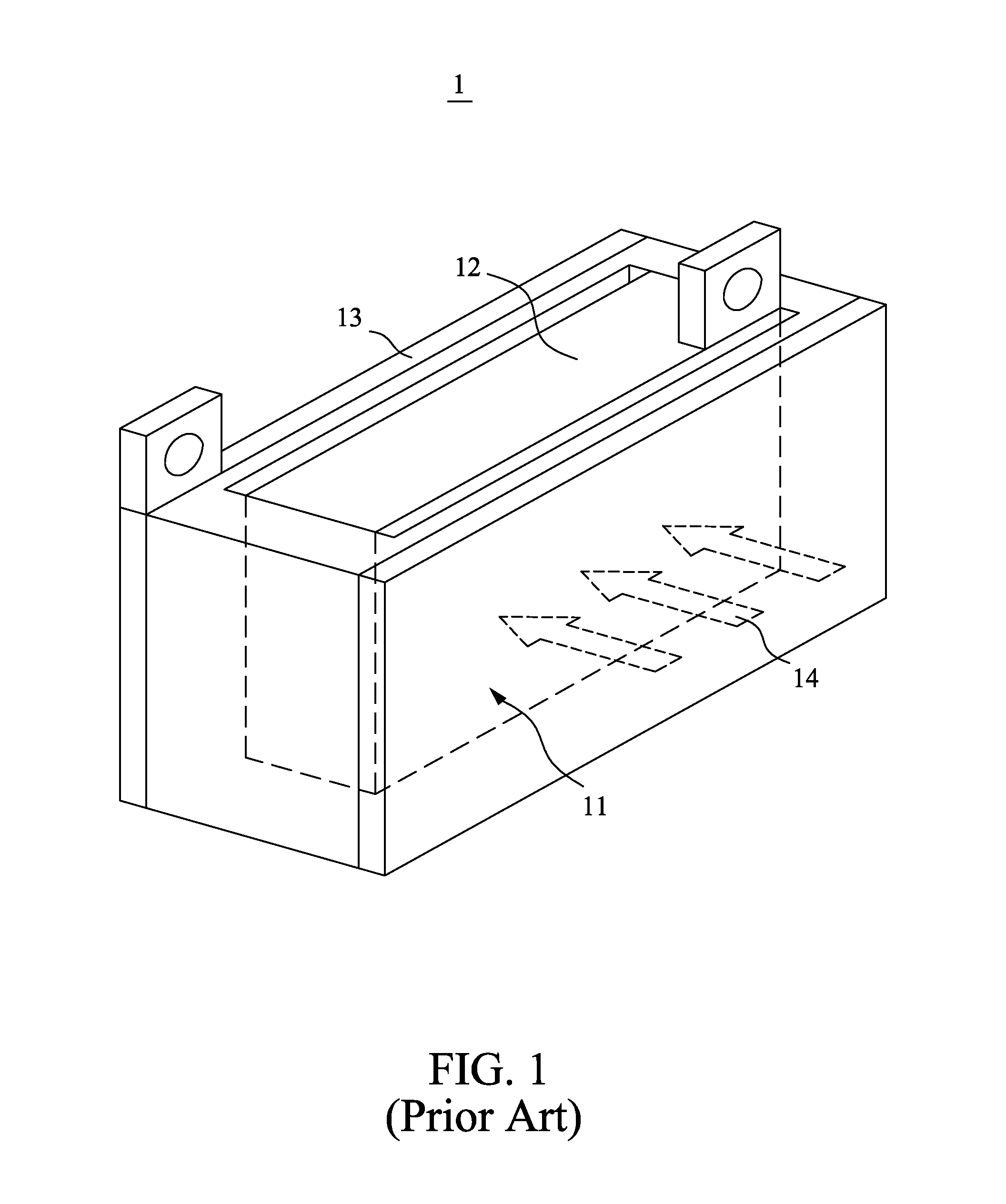
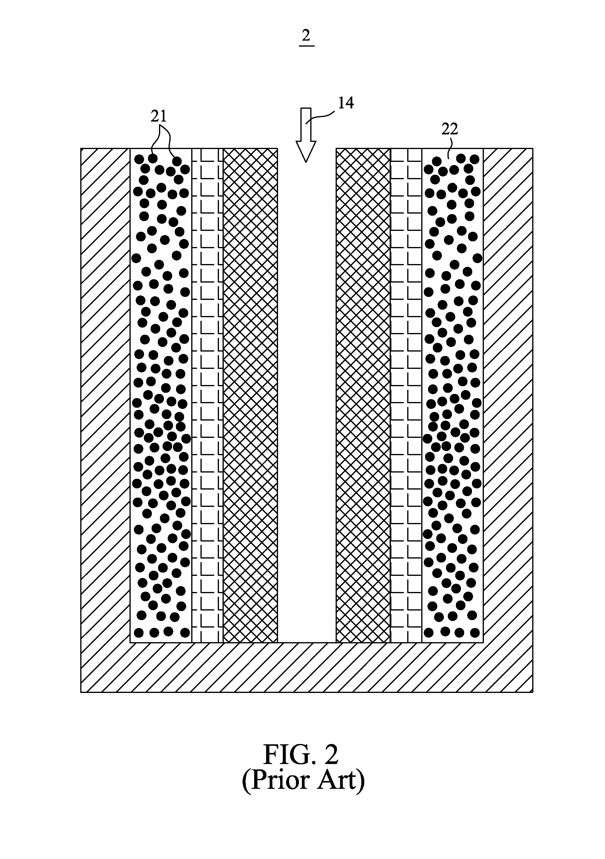
In summary, the drawbacks of the aforementioned prior art may be provided as follows: (I) after completion of reaction of the zinc air fuel cell, the fuel, after complete oxidation of the fuel, must be replaced or supplemented, and waste may be produced to pollute the environment, such that the fuel must be additionally refilled or replaced; and (II) the anode electrode fuel is a solid or semi-solid type, such that the area in contact with the air reaction is limited.

Method used


Image

  • Flow type zinc air fuel cell
  • Flow type zinc air fuel cell
  • Flow type zinc air fuel cell

Examples


Embodiment Construction

[0033]The accompanying drawings are included to provide a further understanding of the invention, and are incorporated in and constitute a part of this specification. The drawings illustrate the preferred exemplary embodiments of the invention and, together with the description, serve to explain the principles of the invention.

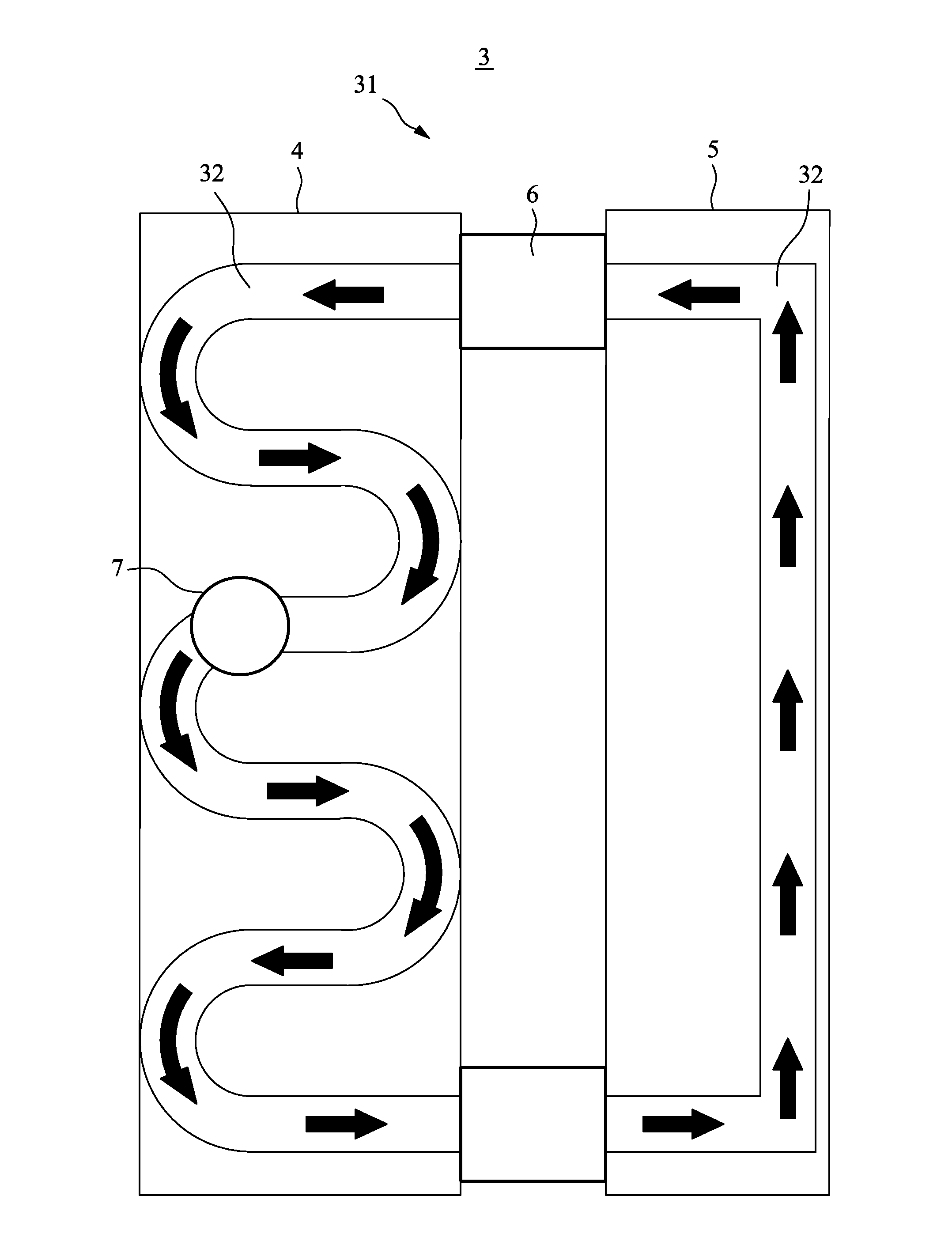
[0034]Referring to FIG. 3 and FIG. 4, in accordance with a preferred exemplary embodiment of the present invention, the flow type zinc air fuel cell 3 of the present invention may include a closed pipeline 31. The air or oxygen from the outside (as shown by the arrows in the drawings) may enter the interior of the flow type zinc air fuel cell via the various arc shaped angles. The flow type zinc air fuel cell may be mainly made up of three parts: a discharging pipeline 4, a charging pipeline 5 and at least one driving device 6. The charging pipeline 5 may be in connection with the two opposite ends of the discharging pipeline 4. In accordance with a preferred ...


PUM


Abstract

The present invention provides a flow type zinc air fuel cell. The flow type zinc air fuel cell is a closed pipeline. The closed pipeline includes a discharging pipeline and a charging pipeline that is in connection with the discharging pipeline. In addition, the charging pipeline includes a flow type zinc electrode that is in a slurry state. The outer periphery of the zinc electrode is encapsulated by a metal electricity collecting pipe. Subsequently, the outer periphery of the metal collecting electricity pipe is encapsulated by an insulating film. Then, the outer periphery of the insulating film is encapsulated by an air electrode. After that, the outer periphery of the air electrode is encapsulated by a housing comprising a plurality of through holes that enable air to enter the air electrode. At least one driving device exists in between the discharging pipeline and the charging pipeline. Subsequent to an oxidation of the zinc electrode in the discharging pipeline, the zinc electrode is driven to the charging pipeline by the driving device. In addition, the zinc electrode is gradually reduced in the charging pipeline, and the zinc electrode is pushed to the discharging pipeline by the driving device, to form a continuous cyclical oxidation and reduction reaction that generates electricity.

Description

FIELD OF THE INVENTION[0001]The present invention relates generally to a fuel cell having an oxidation reduction reaction with air by means of a zinc material, and more particularly, the present invention relates to a zinc air fuel cell that enables a negative electrode (an anode) which comprises zinc material to be designed for carrying out reaction with air in a slurry state, and also enabling the fuel cell to continuously carry out an oxidation reduction reaction without having to supplement or replace the negative electrode (an anode) material or without having to remove any waste.BACKGROUND OF THE INVENTION[0002]Energy is the driving force of economic development, and it is also a measure of overall national strength. In addition, energy is an important indicator of the degree of development of the national culture, the living standards of people and the social progress of history. This shows that every breakthrough in energy technology innovation and development of the product...

Claims


Application Information

Patent Timeline
IPC IPC(8): H01M8/06H01M10/46H01M12/08H01M4/134H01M8/04
CPCH01M8/0656H01M4/134H01M10/46H01M12/08H01M8/04201H01M8/188H01M10/4214Y02E60/10Y02E60/50H01M50/1385
Inventor LIAO, WEN HUANG
Owner LIAO WEN HUANG
Learn More