Current interruption device and electricity storage device using the current interruption device
a technology of electricity storage device and current interruption device, which is applied in the direction of secondary cell servicing/maintenance, cell components, batteries, etc., can solve the problems of battery (casing) swelling, casing breaking, and internal pressure inside the casing (internal pressure) may increase, so as to prevent the pressure of the second space from rising, the effect of operating stably and preventing deterioration
- Summary
- Abstract
- Description
- Claims
- Application Information
AI Technical Summary
Benefits of technology
Problems solved by technology
Method used
Image
Examples
first embodiment
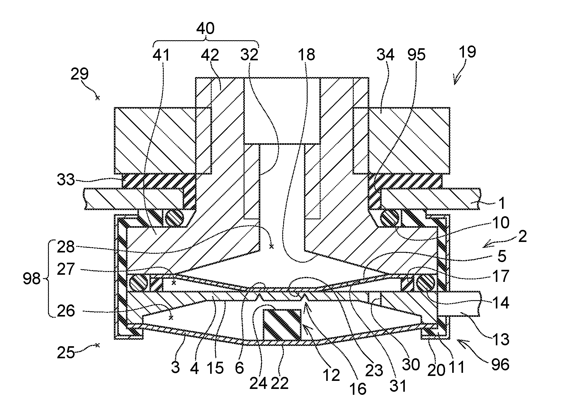
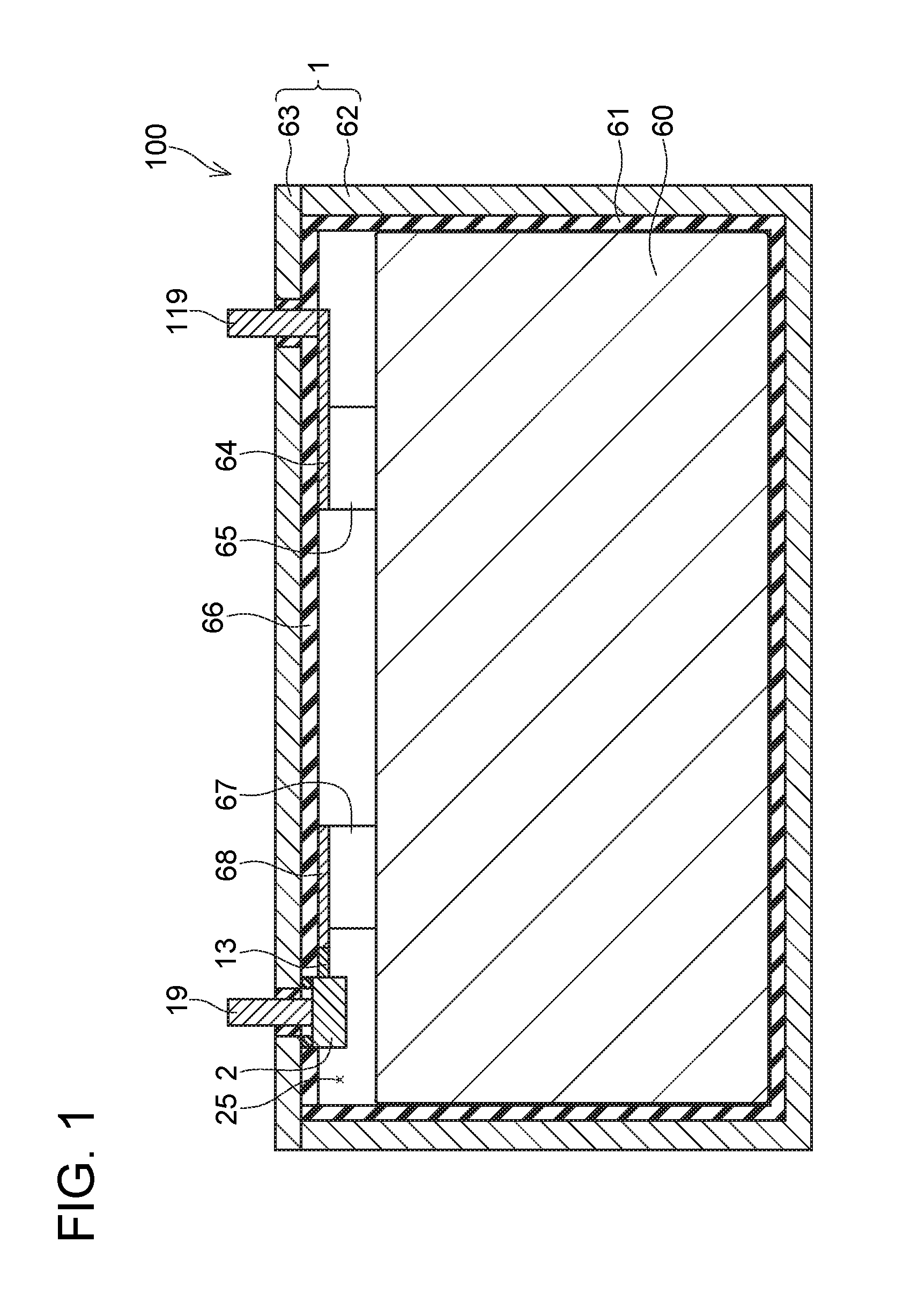
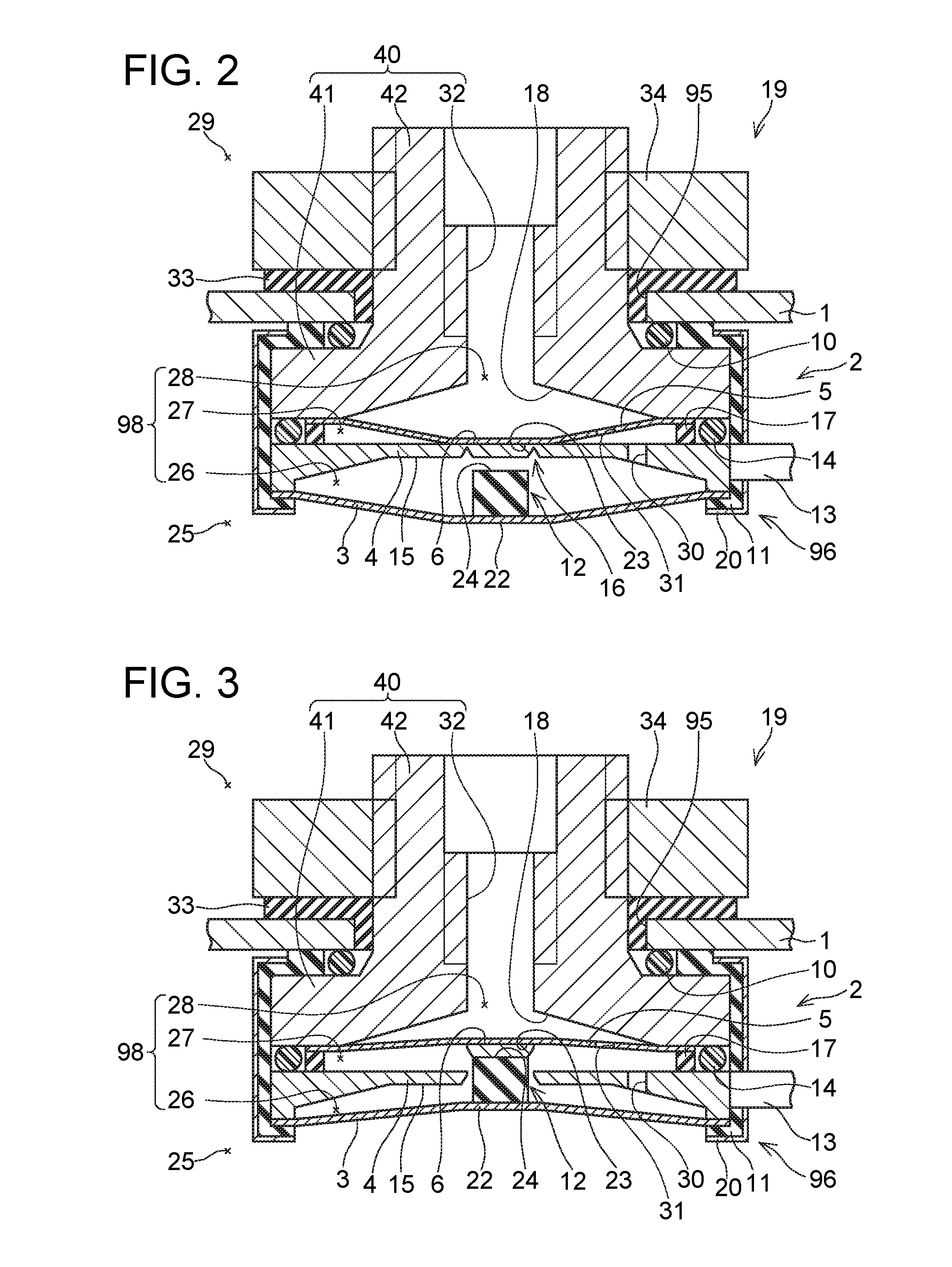
[0043]As shown in FIG. 1, an electricity storage device 100 comprises a casing 1, an electrode assembly 60, a negative terminal 19, a positive terminal 119, and a current interruption device 2. The casing 1 comprises a rectangular box-shaped main body part 62, and a rectangular plate-shaped cover pert 63 that closes the main body part 62. The main body part 62 and the cover part 63 are made of metal (for example, stainless steel, aluminum). In the following description, the main body part 62 and the cover part 63 may simply be termed the casing 1. A space 25 inside the casing 1 stores therein the electrode assembly 60 provided with a positive electrode and a negative electrode. The casing 1 and the electrode assembly 60 are insulated by an insulating sheet 61. A positive tab 65 is fixed to the positive electrode. A negative tab 67 is fixed to the negative electrode.
[0044]The negative terminal 19 and the positive terminal 119 are fixed to the casing 1 (cover part 63). Although not sh...
second embodiment
[0075]An electricity storage device 100 of the second embodiment modifies the current interruption device 2 of the electricity storage device 100 of the first embodiment to a current interruption device 203 (FIG. 6, FIG. 7). The current interruption device 2 of the first embodiment comprised the contact plate 5 and the conduction plate 4. With respect to this, the current interruption device 203 of the second embodiment comprises a contact plate 92 and a conduction plate 36. The conduction plate 4 comprised the breakable groove 16. With respect to this, the conduction plate 36 comprises a through hole 37. The through hole 37 is provided at a center portion of the conduction plate 36. The projection 12 can pass through the through hole 37. A second contact portion 93 of the contact plate 92 is provided around the through hole 37. That is, when the current interruption device 203 is seen in a plan view, the second contact portion 93 is provided on an outside of the through hole 37.
[00...
third embodiment
[0077]An electricity storage device 100 of the third embodiment modifies the current interruption device 2 of the electricity storage device 100 of the first embodiment to a current interruption device 205 (FIG. 8). The current interruption device 205 differs from the current interruption device 2 of the first embodiment in regards to a structure of the insulating projection 12 (specifically, of a configuration corresponding to the projection 12 of the first embodiment). In the current interruption device 205, the insulating projection 12 is configured of a contacting member 75 and a cap 74. The contacting member 75 and the cap 74 are arranged between the deforming plate 3 and the conduction plate 4. The contacting member 75 is arranged at a center portion on an upper surface of the deforming plate 3. The contacting member 75 for example has a cylindrical shape, and is arranged so as to be standing upright relative to the deforming plate 3. Metal, for example, may be used as a mater...
PUM
| Property | Measurement | Unit |
|---|---|---|
| internal pressure | aaaaa | aaaaa |
| current | aaaaa | aaaaa |
| pressure | aaaaa | aaaaa |
Abstract
Description
Claims
Application Information
 - R&D Engineer
- R&D Manager
- IP Professional
- Industry Leading Data Capabilities
- Powerful AI technology
- Patent DNA Extraction
Browse by: Latest US Patents, China's latest patents, Technical Efficacy Thesaurus, Application Domain, Technology Topic, Popular Technical Reports.
© 2024 PatSnap. All rights reserved.Legal|Privacy policy|Modern Slavery Act Transparency Statement|Sitemap|About US| Contact US: help@patsnap.com


