
Electric motor with redundant electric circuits

a technology of electric circuits and electric motors, applied in the direction of motor/generator/converter stoppers, dynamo-electric converter control, magnetic circuit shape/form/construction, etc., can solve the problems of relatively heavy and cumbersome solutions, and achieve the effect of significant space for windings

Inactive Publication Date: 2016-06-30
SAFRAN ELECTRONICS & DEFENSE
View PDF14 Cites 3 Cited by
  • Summary
  • Abstract
  • Description
  • Claims
  • Application Information

AI Technical Summary

Benefits of technology

The invention is a motor that has multiple electric circuits to control it, so that if one circuit fails, the motor can still operate safely. This reduces the weight and complexity of the motor, especially for motors with a limited motion space. The winding can also be provided on each sector to simplify the production of the stator.

Problems solved by technology

Such solution is relatively heavy and cumbersome.

Method used


Image

  • Electric motor with redundant electric circuits
  • Electric motor with redundant electric circuits

Examples


second embodiment

[0038]The elements identical with or similar to those described above are given the same reference numbers in the following description of the invention.

first embodiment

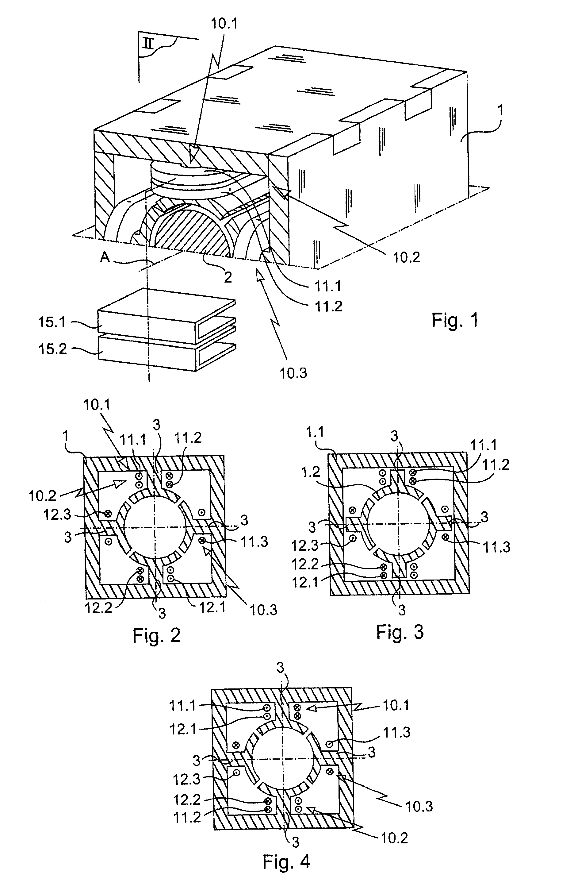
[0039]The motor in FIG. 5 is identical with that of the first embodiment except for the windings 11, 12 of each one of the first and second electric circuits 10.1, 10.2, which are mounted on the same pole of the first pair of poles.

[0040]More precisely, the windings 11.1, 12.1 of the first electric circuit 10.1 enclose one of the teeth 3 of one of the two pairs of teeth and the windings 11.2, 12.2 of the second electric circuit 10.2 enclose the other one of the teeth 3 of the same pair of teeth 3.

[0041]As mentioned above, the winding 11.3 and the winding 12.3 of the third electric circuit 10.3 each enclose one of the teeth 3 of the other pair of teeth 3.

[0042]Of course, the invention is not limited to the described embodiments but encompasses any alternative solution within the scope of the invention as defined in the claims.

[0043]More particularly, the number n of electric circuits and the number N of pairs of poles may be different from three and two.

[0044]The motor may not includ...


PUM


Abstract

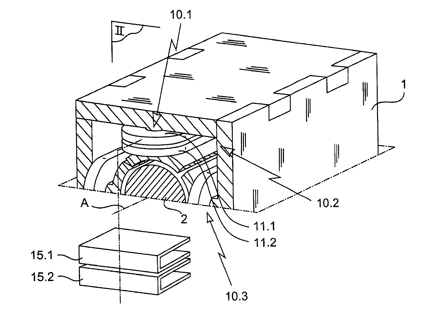
An electric motor having a stator defining a number N, at least equal to two, of pairs of poles and a rotor mounted to pivot in the stator. The motor has a number n of electric circuits each defining two windings mounted on poles of the stator, the windings of all the circuits being substantially identical to each other, the number n of electric circuits being greater than the number N of pairs of poles and at least first and second electric circuits being mounted on a first of the pairs of poles and a third of the electric circuits being mounted on a second of the pairs of poles.

Description

BACKGROUND OF THE INVENTION[0001]1. Field of the Invention[0002]The present invention relates to an electric motor, more particularly a single-phase motor.[0003]2. Brief Discussion of the Related Art[0004]Such single-phase motors are for example used for moving flying surfaces in an aircraft equipped with electric flight controls.[0005]Such electric motor comprises a stator defining a number at least equal to two, of pairs of poles and a rotor mounted to pivot in the stator. The motor comprises an electric circuit defining identical windings mounted on the poles of the stator so as to form the motor phases. The motor may be so arranged as to require a limited motion space. The desired motion space for the motor determines the number of pairs of poles: if one pair of poles is enough for a 180° maximum motion space, two pairs of poles are required for a 90° maximum motion space and three pairs of poles are required for a 60° maximum motion space.[0006]For safety reasons, and more part...

Claims


Application Information

Patent Timeline
Patent Type & Authority Applications(United States)
IPC IPC(8): H02P25/22H02K1/14H02K3/28
CPCH02P25/22H02K1/14H02K3/28H02K1/148H02K3/38H02K5/04H02K2213/06
Inventor PIATON, JEROMEELIE, PHILIPPE
Owner SAFRAN ELECTRONICS & DEFENSE
Learn More