

Integrated Dental Implant Abutments
a dental implant and integrated technology, applied in the field of dental implant abutments, can solve the problems of root loss, visible part of the tooth, crown,
- Summary
- Abstract
- Description
- Claims
- Application Information
AI Technical Summary
Benefits of technology
Problems solved by technology
Method used
Image

Examples
Embodiment Construction
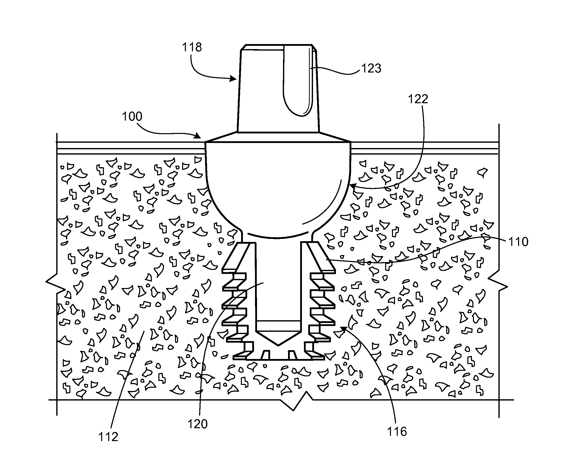
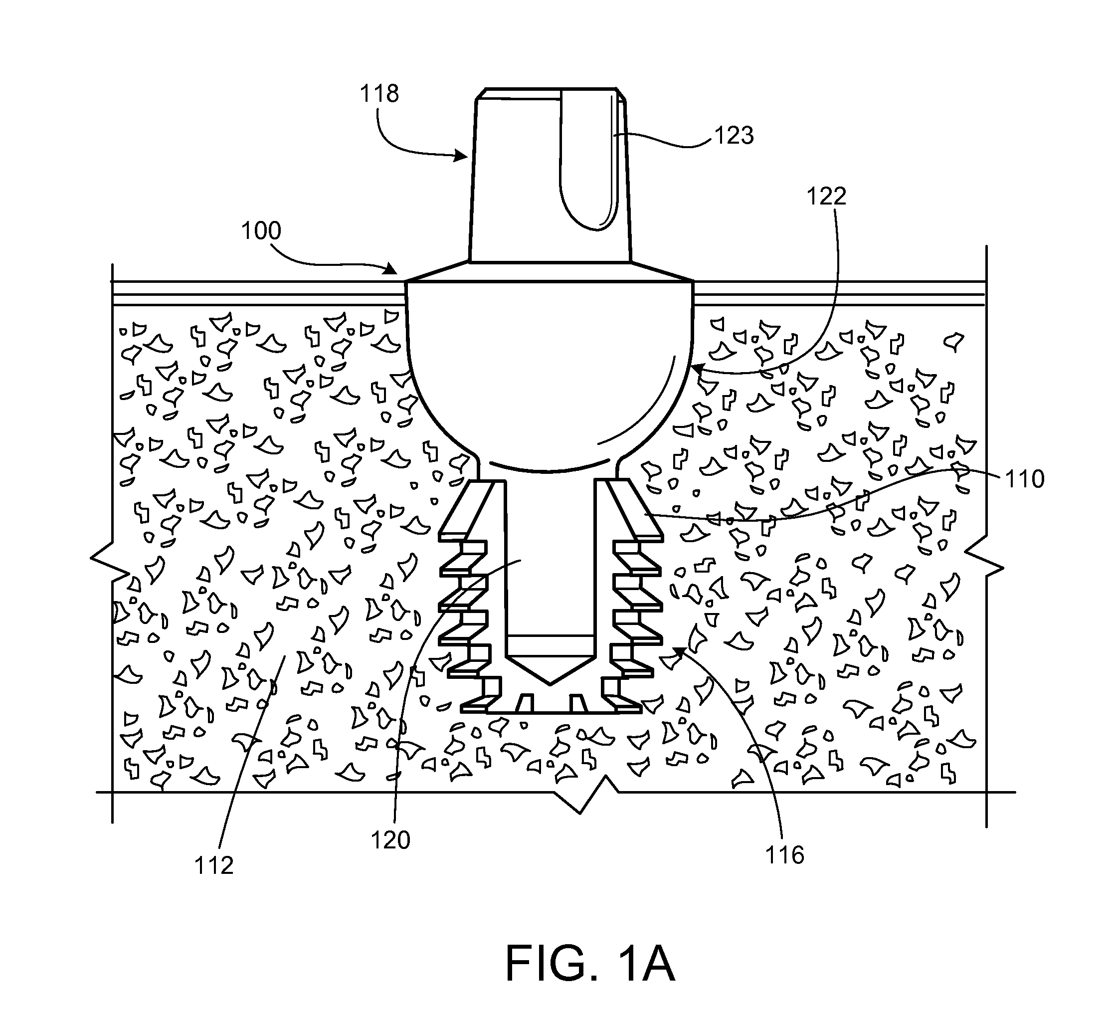
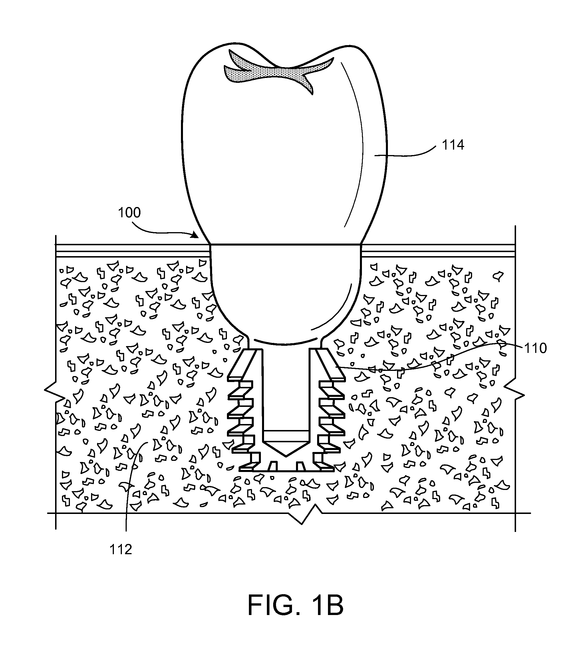
[0017]FIG. 1A shows a dental abutment 100 engaged in a dental implant 110 which has been placed in a patient's jawbone 112. FIG. 1B shows the dental abutment 100 and the dental implant 110 after a crown 114 has been placed on the dental abutment 100.
[0018]The dental abutment 100 in FIG. 1A extends from the apical end 116 (i.e. toward the jaw) to the coronal end 118 (i.e. toward the crown) in the longitudinal direction. The dental abutment 100 has a post 120, which is designed to be received by the open end of the dental implant 110. The post 120 extends from the apical end 116 of the dental abutment 100 to a retention element 122. The dental abutment 100 also has a coronal portion (or head) 123 which designed to support the crown 114. The coronal portion 123 extends from the coronal end 118 of the dental abutment 100 to the retention element 122.
[0019]The dental abutment 100 can be made out of a variety of materials, including titanium alloy or polyether ether ketone (PEEK).
[0020]FI...
PUM
 Abstract
Description
Claims
Application Information