Anesthetic dispensing device

a technology for anesthetics and dispensing elements, which is applied in the direction of medical devices, inhalators, other medical devices, etc., can solve the problems of reducing the effect of anesthetic concentration, requiring considerable technical effort, and reducing the effect of evaporation outpu

Active Publication Date: 2016-07-07
DRAGERWERK AG
View PDF12 Cites 2 Cited by
  • Summary
  • Abstract
  • Description
  • Claims
  • Application Information

AI Technical Summary

Benefits of technology

[0017]According to another embodiment of the present invention, a heating element is provided for the heating of the evaporation chamber at least at times. Such a heating device may be designed, e.g., in the form of a heating element integrated into a wick. In this case, the control signal is preferably generated for adjusting the valve opening, taking a control signal for the heating element into account. As an alternative or in addition a control signal may be generated for the heating element taking into account an adjustment of the valve opening and / or of the control signal for adjusting the valve opening. In this case also, it is, in contrast to conventional anesthetic evaporators, possible to carry out the splitting of the carrier gas stream into a partial gas stream flowing through the bypass channel and a partial gas stream flowing through the dispensing channel exclusively by means of a specific adjustment of the dispensing gap, i.e., especially without having to adjust the bypass gap indirectly or directly as a function of a change in temperature. This can, above all, be attributed to the fact that the influence of the temperature-dependent saturation concentration in the evaporation chamber can be compensated by an automatic change in the dispensing gap. This heating element, which is additionally provided according to this special embodiment, preferably combined with a coupled actuation of the heating element and the valve element, counteracts a cooling off of the evaporation chamber and in this way supports temperature compensation, such that comparatively high evaporation outputs and the increases in the anesthetic concentration connected therewith can also be achieved. Above all, rapid changes can also take place in a comparatively large area.

Problems solved by technology

It is problematic in the solutions known from the state of the art that, on the one hand, that a temperature compensation is accomplished with comparatively complicated measures.
In particular, the selection of suitable materials as well as the manufacture and the adjustment of correspondingly accurately adjustable dispensing elements require a considerable technical effort and are economically costly.

Method used


Image

  • Anesthetic dispensing device
  • Anesthetic dispensing device
  • Anesthetic dispensing device

Examples


Embodiment Construction

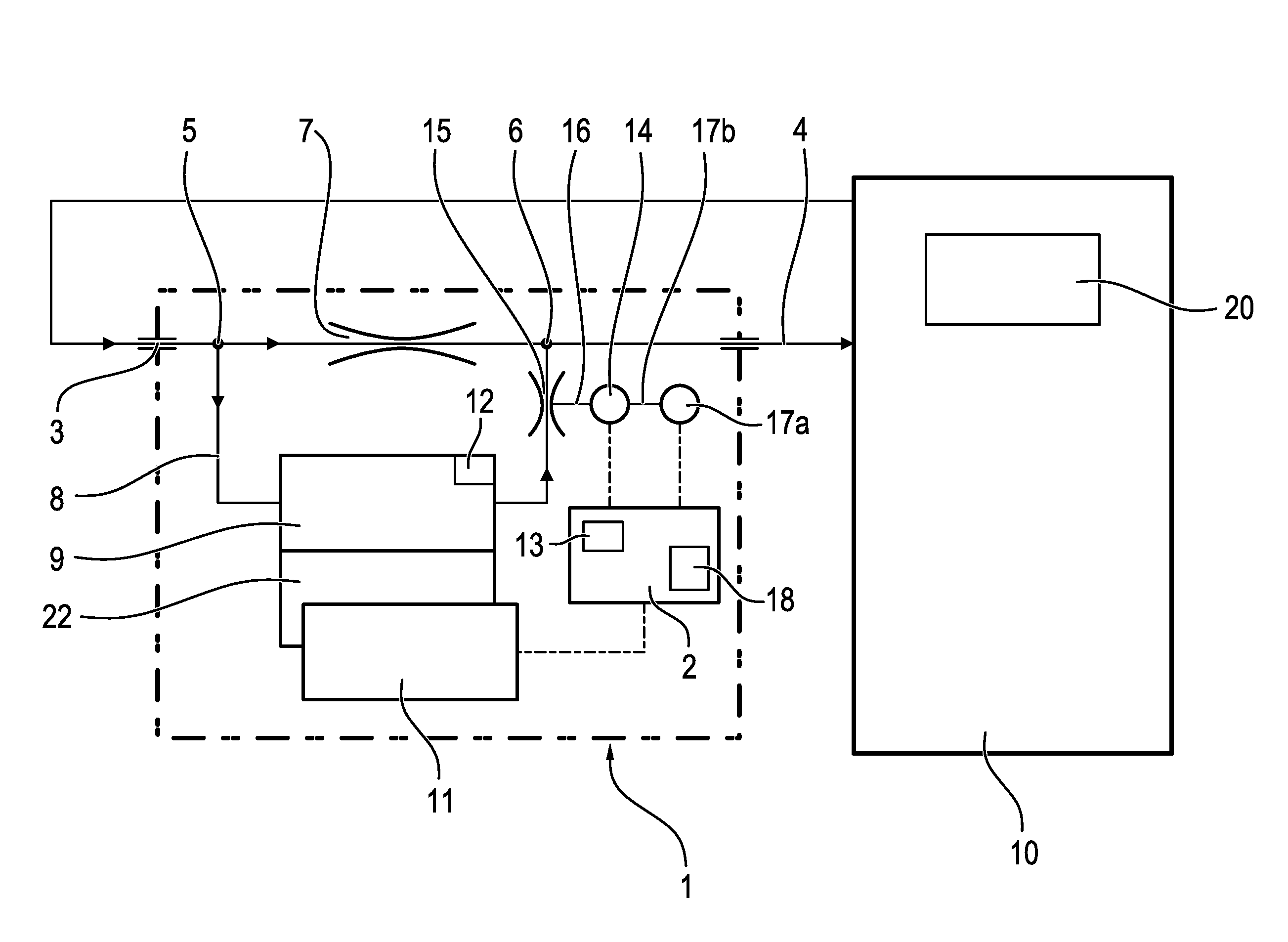
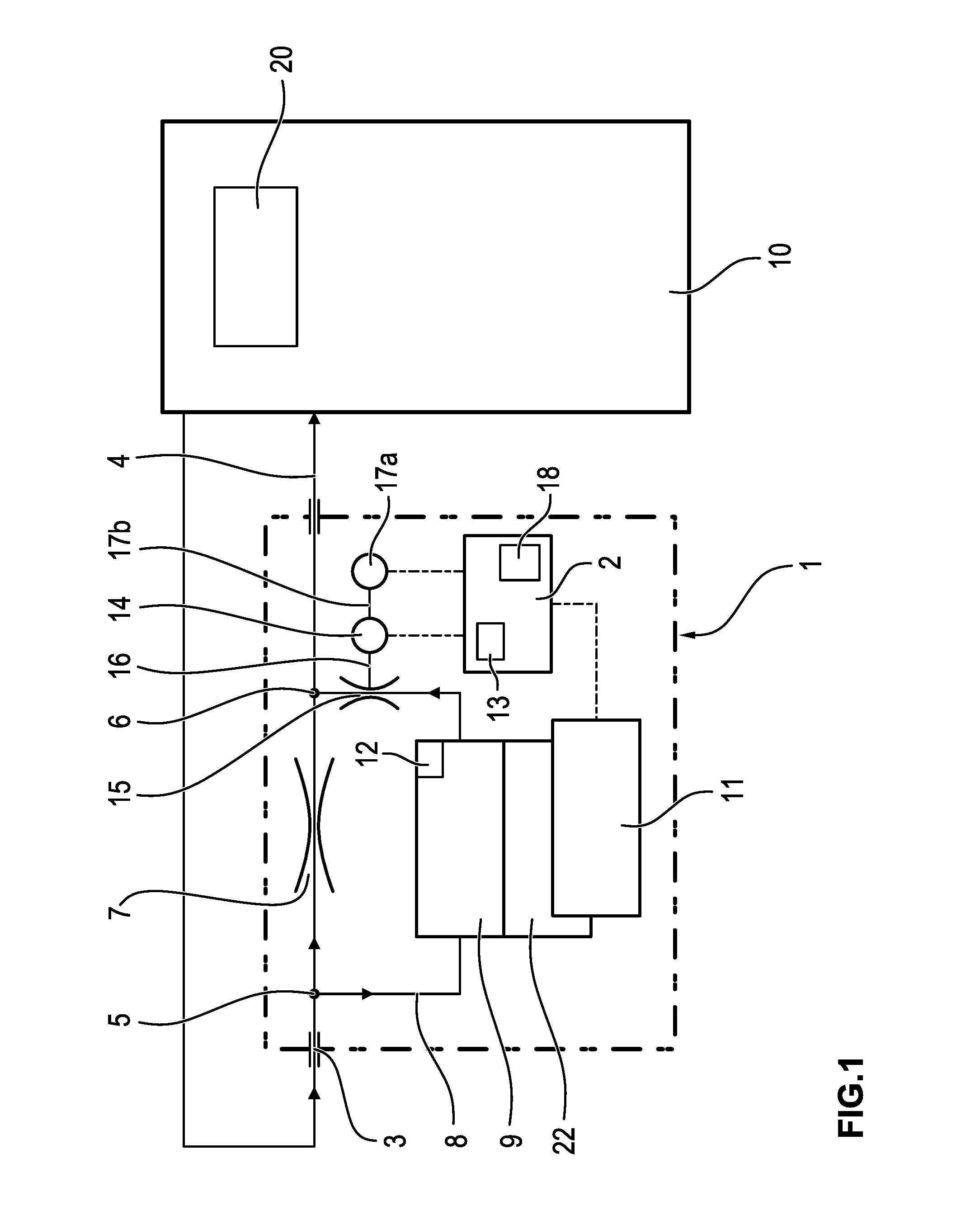
[0026]Referring to the drawings, FIG. 1 shows a schematic view with flow diagram of an anesthetic dispensing device 1 designed according to the present invention, which can be fastened to an anesthesia apparatus 10. The anesthetic dispensing device 1 has a central control unit 2, by means of which the dispensing of anesthetic in a gas stream as needed is ensured. A data link between the anesthetic dispensing device 1 with integrated control unit 2, on the one hand, and the anesthesia apparatus 10, on the other hand, is not shown.

[0027]The carrier gas, especially oxygen-enriched air, flows via a suitable, fluid-tight connection from the anesthesia apparatus 10 into the carrier gas inlet 3 of the anesthetic dispensing device 1. In the area of the carrier gas inlet 3 is located a branch 5, at which the carrier gas stream is split into two partial gas streams, which flow, on the one hand, into a bypass channel 7 and, on the other hand, into a dispensing channel 8. The part of the carrie...


PUM


Abstract

An anesthetic dispensing device (1), to which a carrier gas stream is fed for enriching with anesthetic, has the gas stream split into two partial gas streams, one of which flows through a bypass channel (7) unchanged and the other of which is fed to an evaporation chamber (9), where the partial gas stream is saturated with anesthetic. In a mixing point (6), both partial gas streams are mixed to form an anesthetic gas stream, which leaves the anesthetic dispensing device through the anesthetic gas outlet (4). A control unit (2) is provided that is configured to generate a control signal for an electric motor drive (14) for adjusting the valve opening of the valve element (15) on the basis of a concentration of the anesthetic in the anesthetic gas needed at the anesthetic gas outlet (4) and at least one temperature-specific correction factor.

Description

CROSS REFERENCE TO RELATED APPLICATIONS[0001]This application claims the benefit of priority under 35 U.S.C. §119 of German Patent Application 10 2015 000175.2 filed Jan. 2, 2015, the entire contents of which are incorporated herein by reference.FIELD OF THE INVENTION[0002]The present invention pertains to an anesthetic dispensing device with a carrier gas inlet and with an anesthetic gas outlet, which are connected to one another via a bypass channel and via a dispensing channel arranged parallel hereto in terms of flow. An anesthetic-filled evaporation chamber, through which carrier gas flows, is connected to the dispensing channel, such that the carrier gas is enriched with anesthetic and subsequently flows through the dispensing channel to the anesthetic gas outlet. The variation of the carrier gas volume flow flowing through the evaporation chamber is carried out by means of a valve element, the valve opening of which can be changed as needed.BACKGROUND OF THE INVENTION[0003]An...

Claims


Application Information

Patent Timeline
Patent Type & Authority Applications(United States)
IPC IPC(8): A61M16/10A61M16/20A61M16/00
CPCA61M16/104A61M16/0003A61M16/1075A61M2205/52A61M2202/0241A61M2205/3334A61M2205/3368A61M16/202A61M16/18A61M2205/3365A61M16/204A61M16/024A61M2202/0007
Inventor MANIGEL, JURGENBARTELS, UWERADOMSKI, KLAUS
Owner DRAGERWERK AG
Why Eureka
Try Eureka