Light Bar Assembly and Backlight

a backlight and light bar technology, applied in the field of display technology, can solve the problems of light bar b>4/b> damage, light bar , hard control of the strength of applied force, etc., and achieve the effect of saving cost, improving assembly efficiency of backlight, and greatly reducing damage risk of light bar

Active Publication Date: 2016-07-07
BOE TECH GRP CO LTD +1
View PDF8 Cites 1 Cited by
  • Summary
  • Abstract
  • Description
  • Claims
  • Application Information

AI Technical Summary

Benefits of technology

[0019]According to the present invention, the plurality of extension parts on the light bar fixing tape are respectively matched with the plurality of through holes on corresponding positions on the backplane to fix the light bar on the backplane. Compared with the prior art, the light bar in the present invention is positioned more accurately and conveniently, and the assembly efficiency of the backlight is improved. In addition, under the condition that the light bar needs to be detached to repair the backlight, by adopting the present invention, the damage risk of the light bar can be greatly reduced and the cost is saved.

Problems solved by technology

However, in the process of fixing the light bar 4 via the jig, the strength of an applied force is hard to be controlled, if the strength of the force is too weak, the position of the light bar 4 may deviate from the ideal position; if the strength of the force is too strong, light emitting diodes on the light bar 4 may be damaged.
Further, in a process of detaching the light bar 4 to repair the backlight, the light bar 4 is liable to be torn and the flexible printed circuit board is liable to deform, and this results in severe loss.

Method used


Image

  • Light Bar Assembly and Backlight
  • Light Bar Assembly and Backlight
  • Light Bar Assembly and Backlight

Examples


Embodiment Construction

[0033]A detailed illustration of the specific implementations of the present invention will be given below in conjunction with the accompanying drawings. It should be understood that, the specific implementations described herein are merely used for illustrating and explaining the present invention, rather than limiting the present invention.

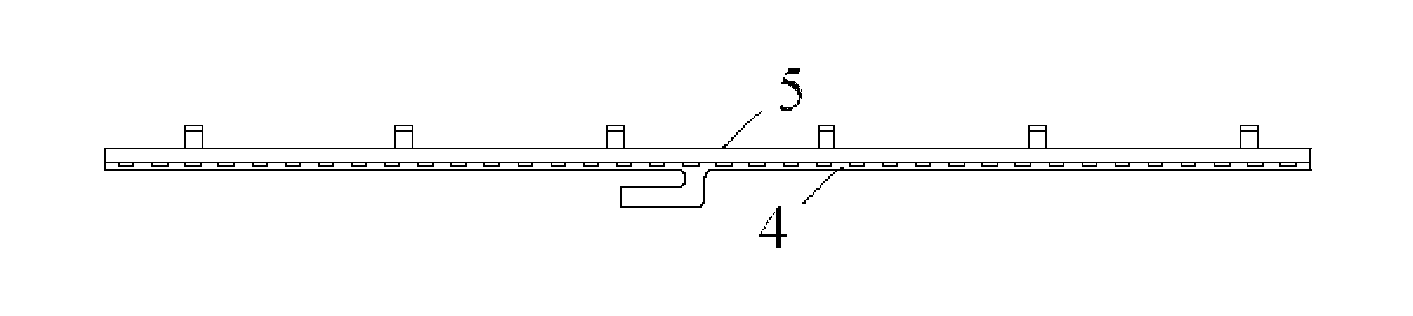
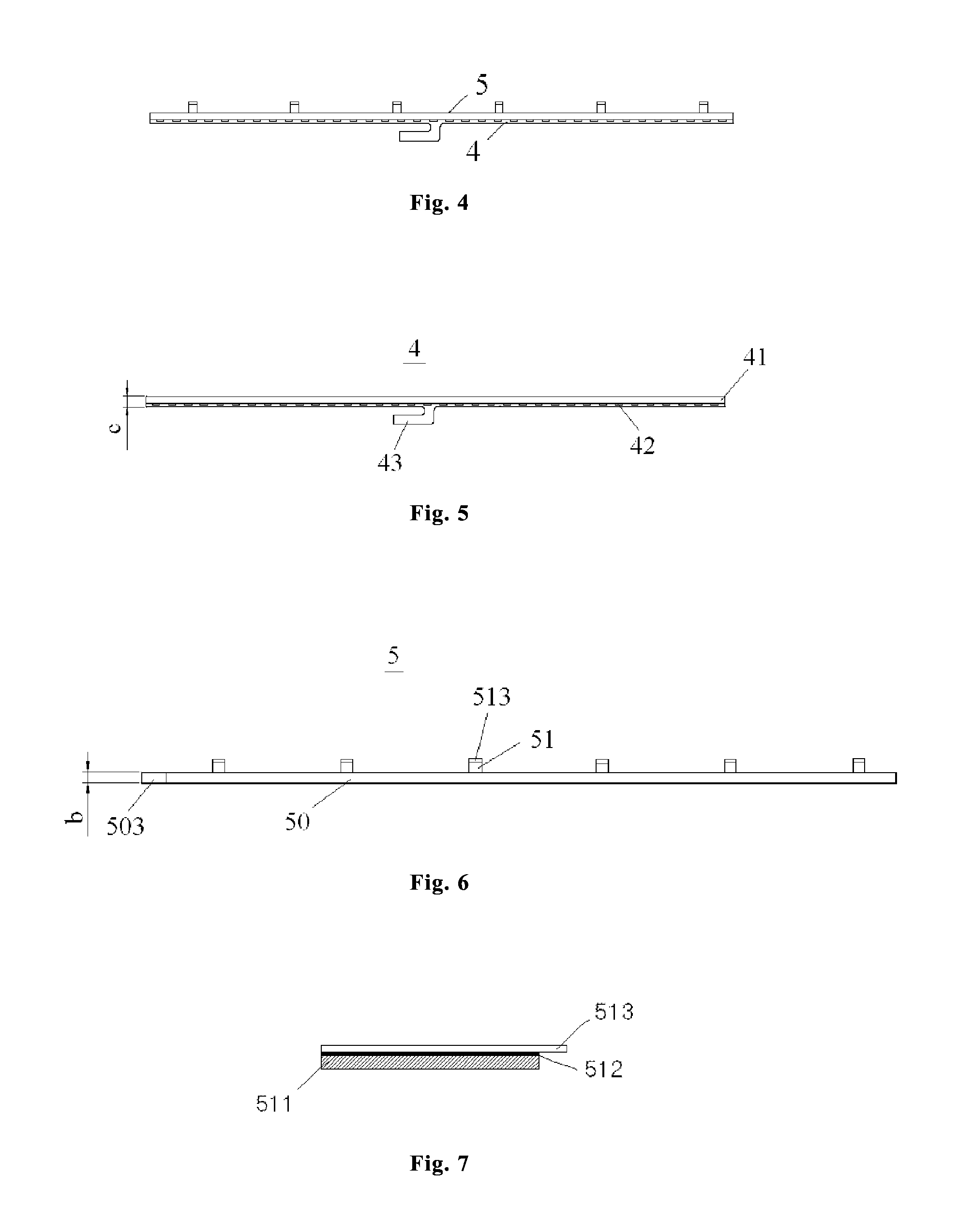
[0034]The embodiment of the present invention provides a light bar assembly at first, FIG. 4 is a schematic diagram of a structure of the light bar assembly, and as shown in FIG. 4, the light bar assembly includes a light bar 4 and a light bar fixing tape 5 arranged on the back surface of the light bar 4.

[0035]FIG. 5 is a schematic diagram of a structure of the light bar 4. As shown in FIG. 5, the light bar 4 includes a flexible printed circuit 41, a plurality of light emitting diodes 42 arranged on the flexible printed circuit 41 and a conductive contact piece 43, wherein one end of the conductive contact piece 43 is connected with the flexible...


PUM


Abstract

The present invention discloses a light bar assembly and a backlight. The light bar assembly includes a light bar and a light bar fixing tape arranged on a back surface of the light bar, wherein the light bar fixing tape includes a main body part and multiple extension parts extending out from the main body part, the main body part is used for being attached to a flexible printed circuit board on the light bar, and the multiple extension parts are used for being attached to a backplane of a backlight to be assembled. The backlight includes a backplane and the light bar assembly, multiple through holes one-to-one corresponding to the positions of the multiple extension parts are formed on the backplane, and each extension part can penetrate through the corresponding through hole and be attached to the back surface of the backplane.

Description

FIELD OF THE INVENTION[0001]The present invention relates to the field of display technology, and in particular relates to a light bar assembly and a backlight including the light bar assembly.BACKGROUND OF THE INVENTION[0002]A liquid crystal display mainly includes a liquid crystal display panel and a backlight. According to the category of light sources, backlights can be divided into light emitting diode (LED) backlights and cold cathode fluorescent lamp (CCFL) backlights. In recent years, the light emitting diode backlights become the best choice in the field of liquid crystal display due to its excellent optical effect and low cost.[0003]In order to obtain an optimal optical effect, a bent part is often arranged on the light source installation position of a backplane of an existing backlight with a small and medium size. FIG. 1 is a schematic diagram of a structure of the existing backlight, and FIG. 2 is an enlarged view of a part A in FIG. 1. As shown in FIG. 1 and FIG. 2, t...

Claims


Application Information

Patent Timeline
Patent Type & Authority Applications(United States)
IPC IPC(8): F21V19/00F21S4/00
CPCF21V19/003F21Y2103/003F21S4/006G02F1/133608F21S4/24G02B6/26
Inventor SUN, WENBOWANG, WEILIU, TONGMINZHANG, QIPINGWANG, XING
Owner BOE TECH GRP CO LTD
Why Eureka
Try Eureka