Ion selective electrode

a selective electrode and electrode technology, applied in the field of electrochemical analytical devices, can solve the problems of difficult assembly, short useful life, clumsy electrode types,

Inactive Publication Date: 2016-07-07
RAO K JAGAN M
View PDF3 Cites 6 Cited by
  • Summary
  • Abstract
  • Description
  • Claims
  • Application Information

AI Technical Summary

Problems solved by technology

This type of electrode is clumsy to make and has a fairly short useful life.
These electrodes gave a somewhat longer life but were difficult to assemble and were not popular because of the obvious drawbacks.
These flow-thru electrodes are difficult to assemble properly and, once assembled, the life of the electrode is very unpredictable.
One of the problems associated with the flow-through electrodes described above is the limited surface area possible if the membrane is to be structurally stable.
The membrane is relatively delicate compared to the tube wall.
While the membrane is bonded to the tube wall, nevertheless, the size of the “interruption” in the tube wall described by the patentees must be limited to a small area into which the membrane is relatively self-supporting.
If the active area of the membrane is too great, it will cease to be self-supporting and will collapse or, at the least, be subject to rupture or breaking with relatively little force.
The limited size of the available active area, therefore, severely limits the amount of plasticizer that can be maintained in the membrane and, therefore, also the amount of dissolved active ingredient.
As a result, many of these structurally stable electrodes of the above described type have a relatively short life under normal use conditions.
However, the material used for the micro-porous tube has very limited number of manufacturers and is quite expensive.
In addition, the manufacturing of the electrodes includes several steps spread over a number of days and there is no known way to speed up the process.
A lot of skilled manual labor was needed to make these electrodes.
This electrode required nine different custom-made parts which contributed to large inventory and cost problems.
The finished electrode has fairly large internal volume so it was not suitable for direct (undiluted) sample measurements.
All these add to the cost of the product.
These are single use devices that cannot be used in flow-through configuration, even though sometimes treated as though they are related to flow-through electrodes.
They do not work with commonly available industrial plastic electrode bodies.

Method used


Image

  • Ion selective electrode
  • Ion selective electrode
  • Ion selective electrode

Examples


Embodiment Construction

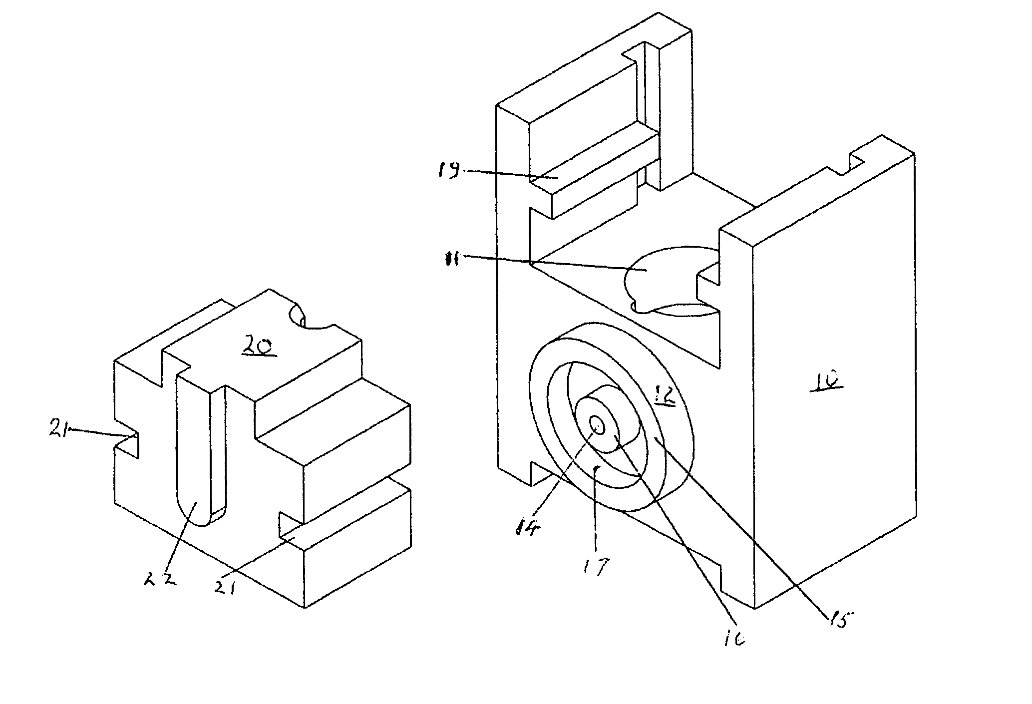
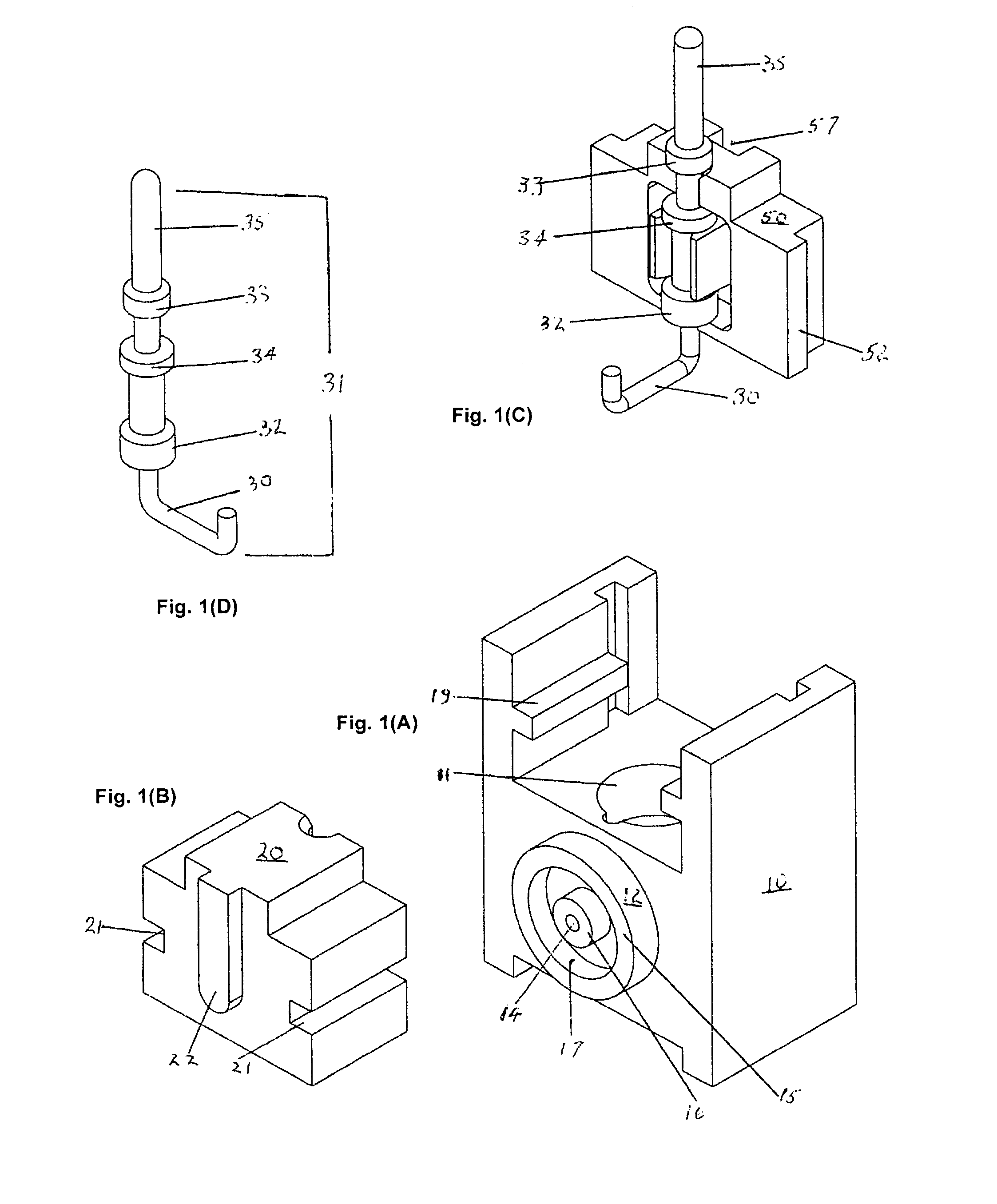
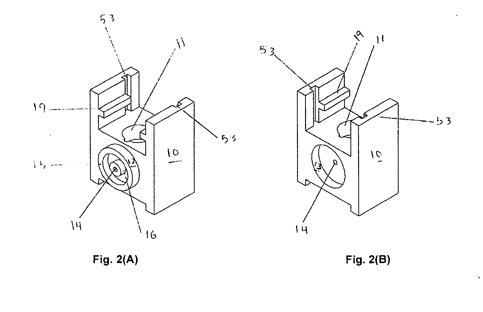
[0019]The present invention embodies a novel linear flow-through electrode As shown in the accompanying drawings, the electrode comprises an electrode body (10), an electrode front cover (20), Electrode back cover (50) and a silver wire internal reference electrode (30) having an electrical connector (31) to connect the electrode to a measuring instrument. The connector typically has a crimping ring (32) for attaching the connector to the silver wire electrode (30), and spacer bushings (33) and (34) for spacing and holding the silver wire electrode and connector assembly in the final flow-through electrode assembly. In FIG. 1, wire 35 will connect directly to the measuring instrument.

[0020]The electrode body has a deep cavity (11) and has one male (12) and one female (13) bushing on either side of the flow path (14) through the body of the electrode. The male bushing (12) has a deep groove (17) between the outer (15) and the inner (16) circles of the bushing. An “O” ring can be inst...


PUM

PropertyMeasurementUnit
thicknessaaaaaaaaaa
thicknessaaaaaaaaaa
thicknessaaaaaaaaaa

Abstract

A five-part internal reference electrode, including a membrane formed in situ, which is useful in automated clinical chemistry analyzers, the method of forming a direct solid state connection to the membrane eliminating the need for the use of an internal reference electrode internal filling solution, and a ganged assembly of said internal reference electrodes with a grounding unit and an external reference electrode.

Description

RELATED APPLICATIONS[0001]This application is a continuation-in-part of U.S. patent application Ser. No. 13 / 727,486, filed Dec. 26, 2012, entitled “Improved Ion Selective Electrode,” the entire contents of which are incorporated fully herein by reference.TECHNICAL FIELD[0002]This invention relates to electrochemical analytical device and particularly to a new and improved ion-selective electrode structure used in the determination of ion (activities) concentrations, and methods for making such structures.BACKGROUND OF THE INVENTION[0003]Ion-selective electrodes are used in clinical chemistry to measure concentration (activity) of ions (like sodium, potassium, chloride and calcium) in blood, serum, plasma cerebrospinal fluid and urine. These devices are used in automated and semi-automated instruments for direct measurements (undiluted samples) or indirect measurements (diluted) of samples. The use of such electrochemical devices for determining and measuring (activity) concentration...

Claims


Application Information

Patent Timeline
Patent Type & Authority Applications(United States)
IPC IPC(8): G01N27/333G01N27/30
CPCG01N27/333G01N27/301G01N27/3335
Inventor RAO, K. JAGAN M.
Owner RAO K JAGAN M
Why Eureka
Try Eureka