
Ion-selective electrode

Inactive Publication Date: 2010-10-07
RAO K JAGAN
View PDF4 Cites 7 Cited by
  • Summary
  • Abstract
  • Description
  • Claims
  • Application Information

AI Technical Summary

Benefits of technology

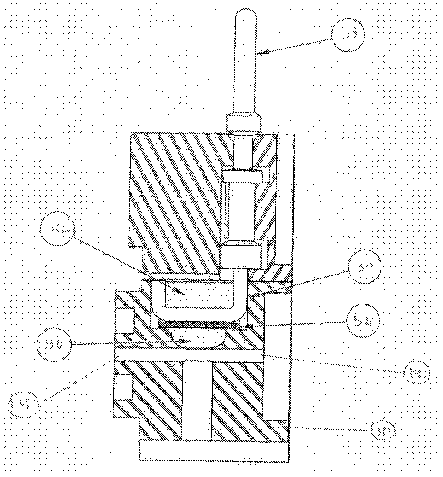
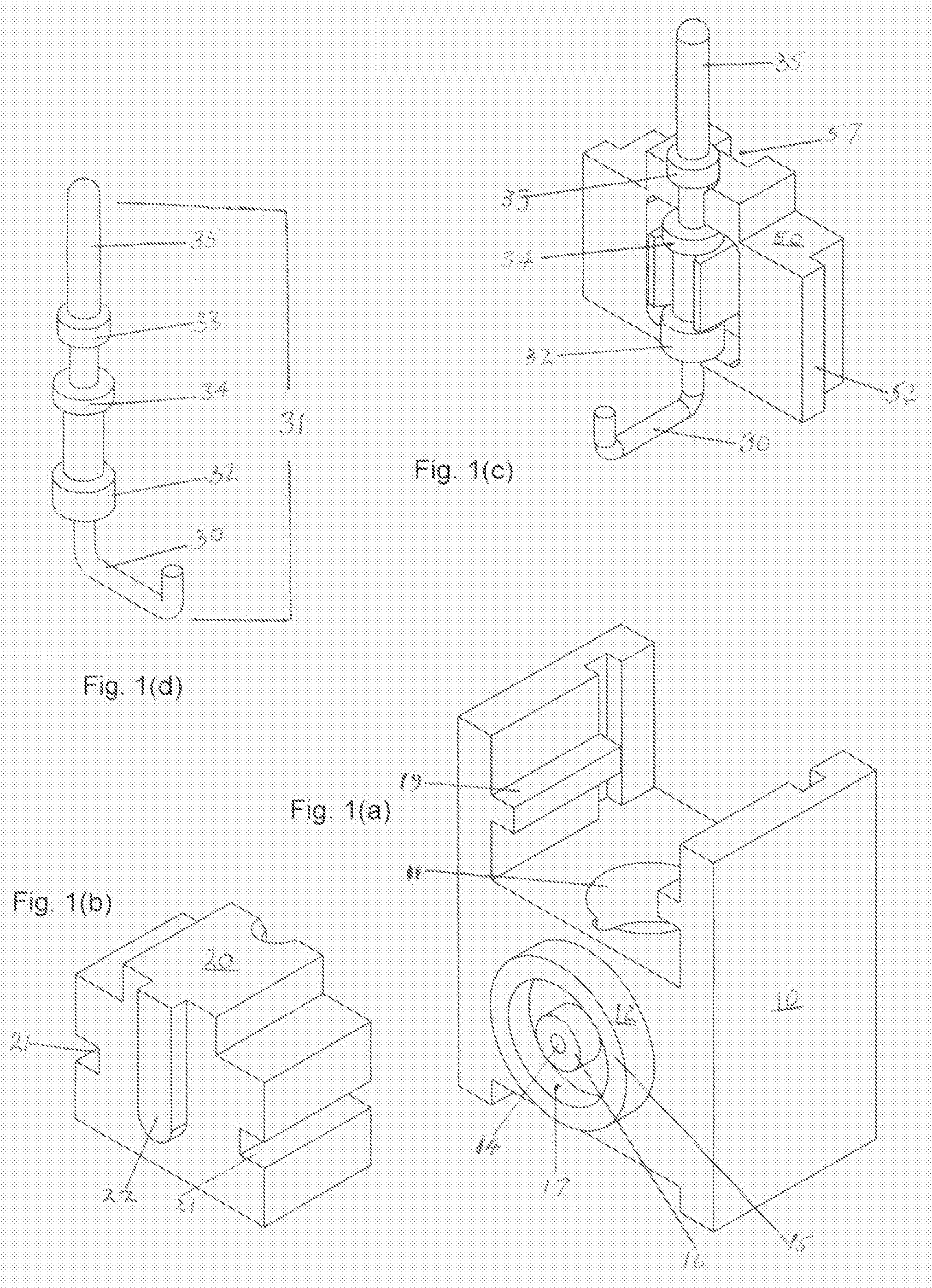
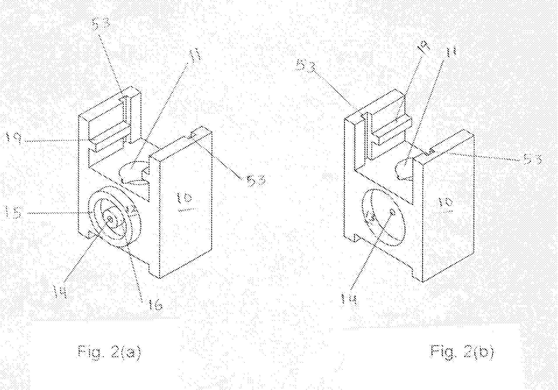
[0006]The present invention comprises a five-part electrode device, counting the membrane formed in situ, which provides substantial improvements over the above noted invention and yet retains all the desirable characteristics and improved performance needed for the device's use in automated clinical chemistry analyzers. It also provides a direct solid state connection to the membrane eliminating the need for the use of internal reference electrode with internal filling solutions. This flow-through electrode can be made in half a day while actually occupying only a few minutes of the manufacturer's time in the conduct of the manufacturing steps. This device uses substantially less active reagent than the older device there by minimizing the use of costly ion-selective reagents and contributing to less expensive product. The manufacturing process for the new device is suitable for semi-automatic operation there by contributing to further reduction of manufacturing costs and providing increased productivity. The new invention electrodes cure in substantially less time (about 15 to 20 days) compared to 90 days for the older electrodes. Thus there is no longer a need to make electrodes ninety or more days in advance; they can be made about 18 or so days before they are needed. This allows for reduced inventory and reduced overhead costs for the product. The new device “exposes” only a small portion of the membrane to the flow path compared to the full length of the membrane in the older design electrodes. Since a smaller portion is exposed compared to the total length of the membrane tube, this device gives substantially longer usage life of the electrode than the older design electrodes. Since it is a solid state electrode without any internal filling solutions, it gives more than two years of shelf life. This is very important for the distributor and the customer.

Problems solved by technology

However, the material used for the micro-porous tube has very limited number of manufacturers and is quite expensive.
In addition, the manufacturing of the electrodes includes several steps spread over a number of days and there is no known way to speed up the process.
A lot of skilled manual labor was needed to make these electrodes.
This electrode required nine different custom-made parts which contributed to large inventory and cost problems.
The finished electrode has fairly large internal volume so it was not suitable for direct (undiluted) sample measurements.
All these add to the cost of the product.

Method used


Image

  • Ion-selective electrode
  • Ion-selective electrode
  • Ion-selective electrode

Examples


examples

[0029]A potassium electrode and a chloride electrode (made with chloride active reagent) made according to the procedure described above were set-up for a life test performance study. The testing was done using a prototype direct sampling Ion-selective electrode instrument. The potassium and chloride electrodes were calibrated using the low and high calibrators and after successful calibration, a batch of 22 pooled human sera samples was run and the % C.V. (Coefficient of Variation) was noted for the run. After running a total of four 22 sample human sera runs, the system was re-calibrated and the process of running 22 cups of pooled human sera four times was repeated. At the end of the day, the electrodes were cleaned with an enzymatic cleaner and conditioned with conditioning solution. All the data was printed and saved. The testing was done for three months. Some days, less than 88 samples were run. During this testing period a total of 3512 pooled human sera samples were run. Fo...


PUM

PropertyMeasurementUnit
Electrical conductoraaaaaaaaaa

Abstract

A five-part electrode device, including a membrane formed in situ, which is useful in automated clinical chemistry analyzers, and the method of forming a direct solid state connection to the membrane eliminating the need for the use of an internal reference electrode requiring internal filling solutions.

Description

RELATED APPLICATIONS[0001]Provisional Patent Application No. 61 / 167,489, the benefit of which is claimed herewith.FEDERALLY SPONSORED RESEARCH AND / OR DEVELOPMENT[0002]None[0003]This invention relates to electrochemical analytical device and particularly to a new and improved ion-selective electrode structure used in the determination of ion(activities) concentrations, and methods for making such structures.BACKGROUND OF THE INVENTION[0004]Ion-selective electrodes are used in clinical chemistry to measure concentration(activity) of ions (like sodium, potassium, chloride and calcium) in blood, serum, plasma, cerebrospinal fluid, urine, fertilizers, and industrial fluids. These devices are used in automated and semi-automated instruments for direct measurements (undiluted samples) or indirect measurements (diluted samples).[0005]Rao, et al, in U.S. Pat. No. 5,013,421 described a flow through type ion-selective lectrode device which uses a micro-porous tubular material impregnated with ...

Claims


Application Information

Patent Timeline
IPC IPC(8): G01N27/26
CPCG01N27/333
Inventor RAO, K. JAGAN
Owner RAO K JAGAN
Learn More