Robotic system

a robot and robot technology, applied in the field of robot systems, can solve the problems of inability to protect the robot designed for use in the operating theatre, the inability to protect and the inability to prevent collisions between the robot and the personnel with absolute certainty, so as to achieve the effect of any risk of injury

Active Publication Date: 2016-07-14
ABB (SCHWEIZ) AG
View PDF4 Cites 6 Cited by
  • Summary
  • Abstract
  • Description
  • Claims
  • Application Information

AI Technical Summary

Benefits of technology

[0027]If the optical axis of the lens coincides with the longitudinal axis of the endoscope, then an extraction movement of the endoscope does not generally present any risk of injury to the patient and can therefore be performed in connection with an evasive movement, if necessary. A rotation of the endoscope around its axis is also generally possible without any risk of injury.

Problems solved by technology

Conversely, due to their considerable mass and rapid movements, these robots are quite capable of injuring personnel working in their vicinity.
Robots which are designed for use in the operating theatre cannot, for practical reasons, be shielded by means of a cage, since in general they do not perform an operation on their own; medical personnel are also working on the same patient at the same time.
A collision between such a robot and the personnel cannot therefore be prevented with absolute certainty.
Since a surgical robot is generally lighter and slimmer in construction than a production robot, in order to avoid unnecessarily blocking the personnel's view of a surgical field, in the event of a collision a deflection of the robotic arm cannot be wholly prevented.
If a tool being handled by the robotic arm is also thereby deflected, this could injure the patient.
However, the possibilities for such an evasive movement are limited when the robotic arm is handling a tool on or in the patient's body which may not be moved at will.
However, the number of degrees of freedom of the robotic arm is generally only as large as is necessary in order to perform the desired movements of the tool.
Therefore, there is a not insignificant likelihood that the degrees of freedom of the robotic arm are not sufficient for an evasive movement in which the tool remains immovable.
If the tool is a camera, in particular an endoscope camera, the problem arises that any movement of the camera changes the image which it provides of its surroundings.
Any movement of the camera can therefore lead to a user who is observing the images supplied by the camera on a screen losing sight of an object which is of interest to him.
The monitoring of other objects, in particular of tissue parts of a patient, is not facilitated with this robotic system.
However, if the movement of the lens is attributable to a collision avoiding movement, then the likelihood is high that the user has not selected an object at the decisive moment.
In such a case, the control unit can be configured to vary the zoom factor if a movement of the lens in the direction of its optical axis is an evasive movement, but not to vary the zoom factor if the movement is caused by an external command, because if the user issues a corresponding command while observing the image on the screen then he expects to be able to recognize and assess the movement of the camera on the basis of the change in the relationship between the sizes of objects represented in the image, and failure of an intuitively anticipated change in size to occur can leave the user uncertain whether or not the robotic arm has performed the commanded movement.
Although this would not lead to a change in the size of an object displayed on the screen, the rotation of the image associated with the rotation of the camera can hinder the recognition of the object which is of interest, for which reason the rotation of the image should be at least partially compensated by the image processing unit installed downstream.

Method used


Image

  • Robotic system
  • Robotic system
  • Robotic system

Examples


Embodiment Construction

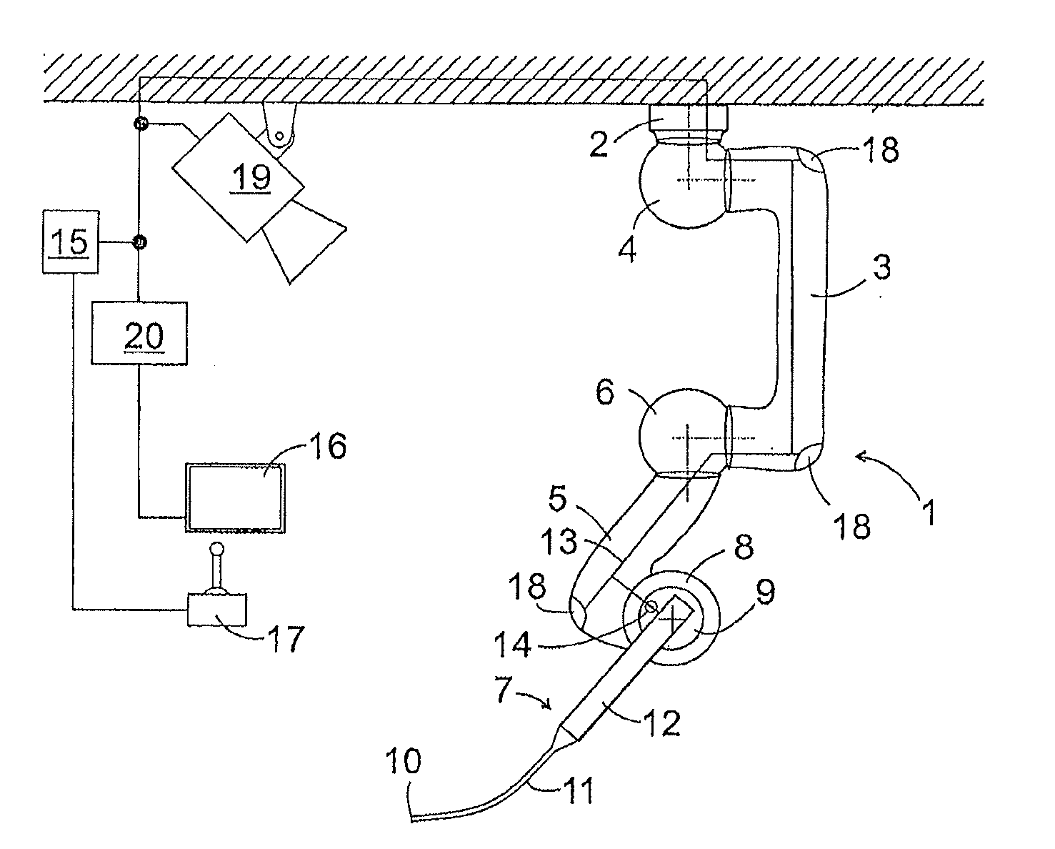
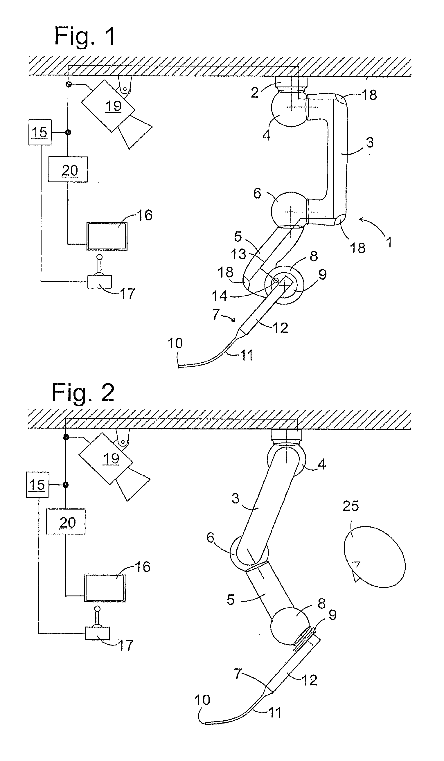
[0035]FIG. 1 shows, in diagrammatic form, a robotic system according to an embodiment of the present invention. The system comprises a robotic arm 1 with a base 2 mounted in fixed position, in this case for example on the ceiling of an operating room, a first arm section 3, which is connected with the base via a first articulated module 4, a second arm section 5 which is connected with the first arm section 3 via a second articulated module 6, and an endoscope 7 which is detachably attached to a holder 9 connected with the second arm section 5 via the articulated module 8.

[0036]The articulated modules 4, 6, 8 are in this case designed as two-axis joints with two shafts arranged orthogonally in relation to one another which are in each case anchored non-rotatingly to an adjacent component of the robotic arm, i.e. the base 2 and the arm section 3 in the case of the module 4, the arm sections 3, 5 in the case of the module 6 and the arm section 5 and the holder 9 in the case of the mod...


PUM


Abstract

A robot system comprises a base (2), a robot arm (1) connected to the base, a camera (10), at least one objective lens in the camera (10) being movable with the robot arm (1), and a screen (16). A control unit (15) is configured to detect a change in the distance between an object (21) detected by the camera (10) and the objective lens, and to vary the zoom factor of a zoom function of the camera (10) according to the change in distance.

Description

TECHNICAL FIELD[0001]The present invention relates to a robotic system, in particular for operating room applications.BACKGROUND INFORMATION[0002]Robots have been widely used for many years in the field of industrial manufacturing where, thanks to their ability to reproduce pre-programmed sequences of operations within a short time, an infinite number of times, they make possible significant rationalizations in production. Since such robots are in most cases also designed to relieve humans of fatiguing working steps like handling heavy workpieces, they are correspondingly robust in construction and at most can only be deflected slightly through an external impact. Conversely, due to their considerable mass and rapid movements, these robots are quite capable of injuring personnel working in their vicinity. In order to avoid a collision with persons, industrial robots are therefore generally surrounded by a cage when in use.[0003]Robots which are designed for use in the operating thea...

Claims


Application Information

Patent Timeline
Patent Type & Authority Applications(United States)
IPC IPC(8): A61B34/32A61B90/00
CPCA61B34/32A61B2090/3614A61B90/37A61B90/361A61B1/00188G02B23/2438A61B1/00006A61B1/00009A61B1/0016A61B1/045A61B2090/364A61B34/30A61B2090/061
Inventor GOMBERT, BERNDKRAUSEN, LEOPOLD
Owner ABB (SCHWEIZ) AG
Why Eureka
Try Eureka