
Aircraft safety device systems

a safety device and aircraft technology, applied in the direction of aircraft power plant components, transportation and packaging, lighter-than-air aircraft, etc., can solve the problems of engine failure risk, subsequent injuries and deaths, and unnecessary repair costs

Active Publication Date: 2016-07-14
JONES RICHARD +1
View PDF8 Cites 8 Cited by
  • Summary
  • Abstract
  • Description
  • Claims
  • Application Information

AI Technical Summary

Benefits of technology

The present invention is a new aircraft safety device system to protect airplane engines from damage caused by airborne objects. It uses a cone-shaped deflecting member mounted at the front of the engine to deflect birds and debris away from the engine. The system is designed to reduce the risk of engine failure, crashes, and subsequent injuries and deaths. The rods provide strength and support for the deflecting member, allowing it to act as a safety device for the engine. This invention can also save money and reduce the risk of injury and death.

Problems solved by technology

Using this device may drastically reduce necessary repair costs, and may also reduce the risk of engine failure, crashes, and subsequent injuries and deaths.

Method used


Image

  • Aircraft safety device systems
  • Aircraft safety device systems
  • Aircraft safety device systems

Examples


Embodiment Construction

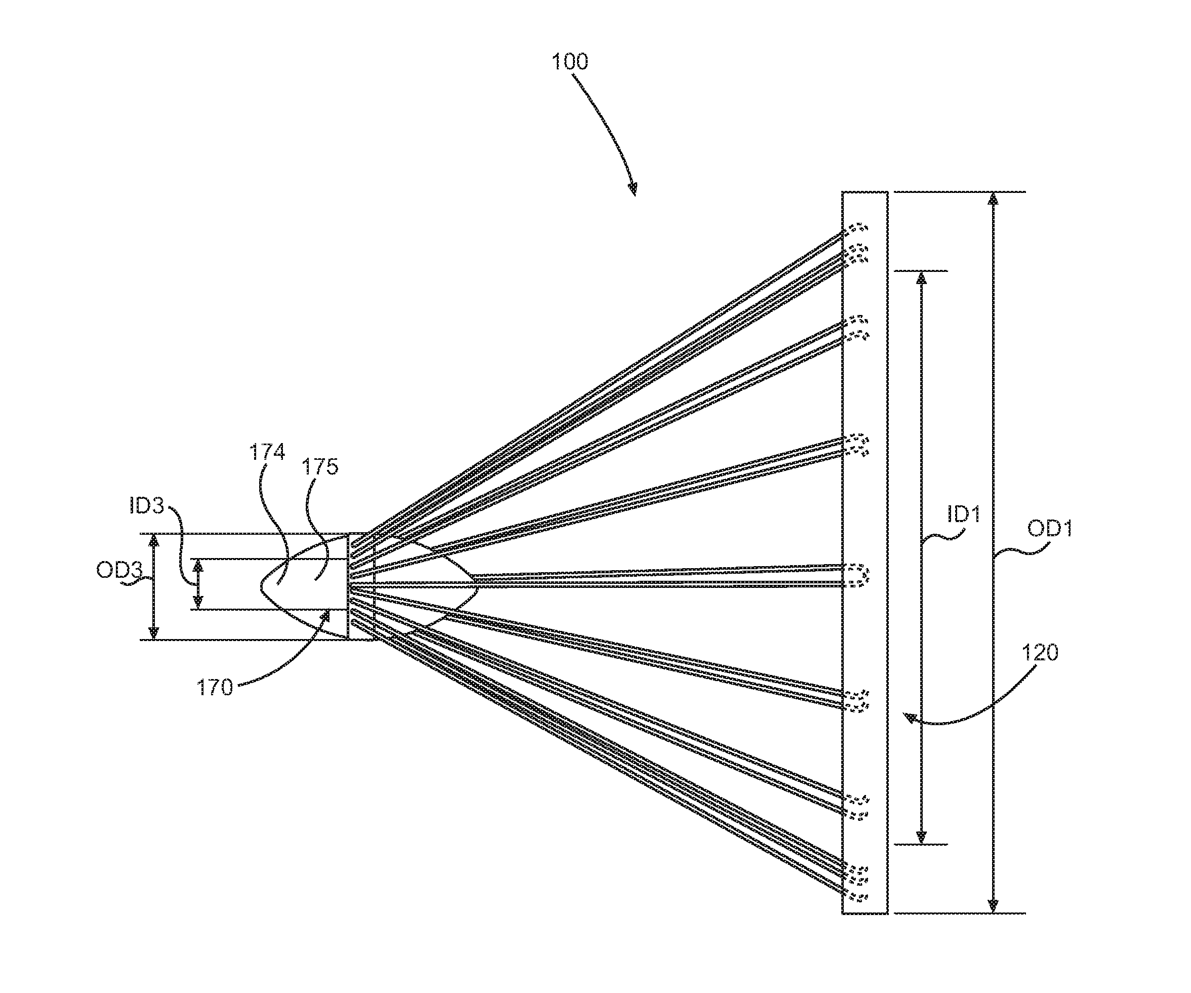
[0026]As discussed above, embodiments of the present invention relate to a field of devices for obstructing the entry of birds and other foreign objects into aircraft jet engines and more specifically relates to a screen of convex rods used to deflect foreign objects from the air intake of a turbine engine.

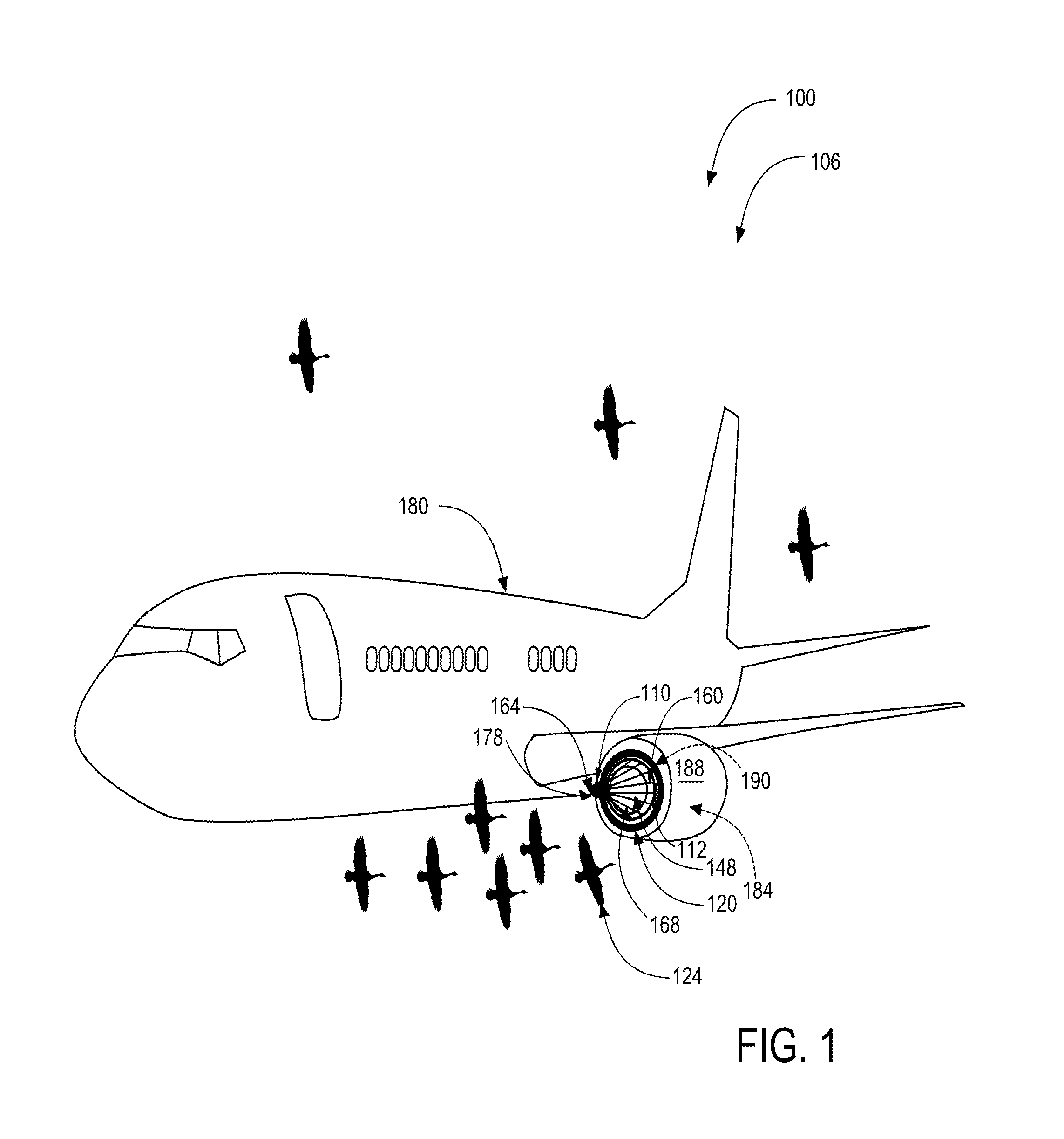
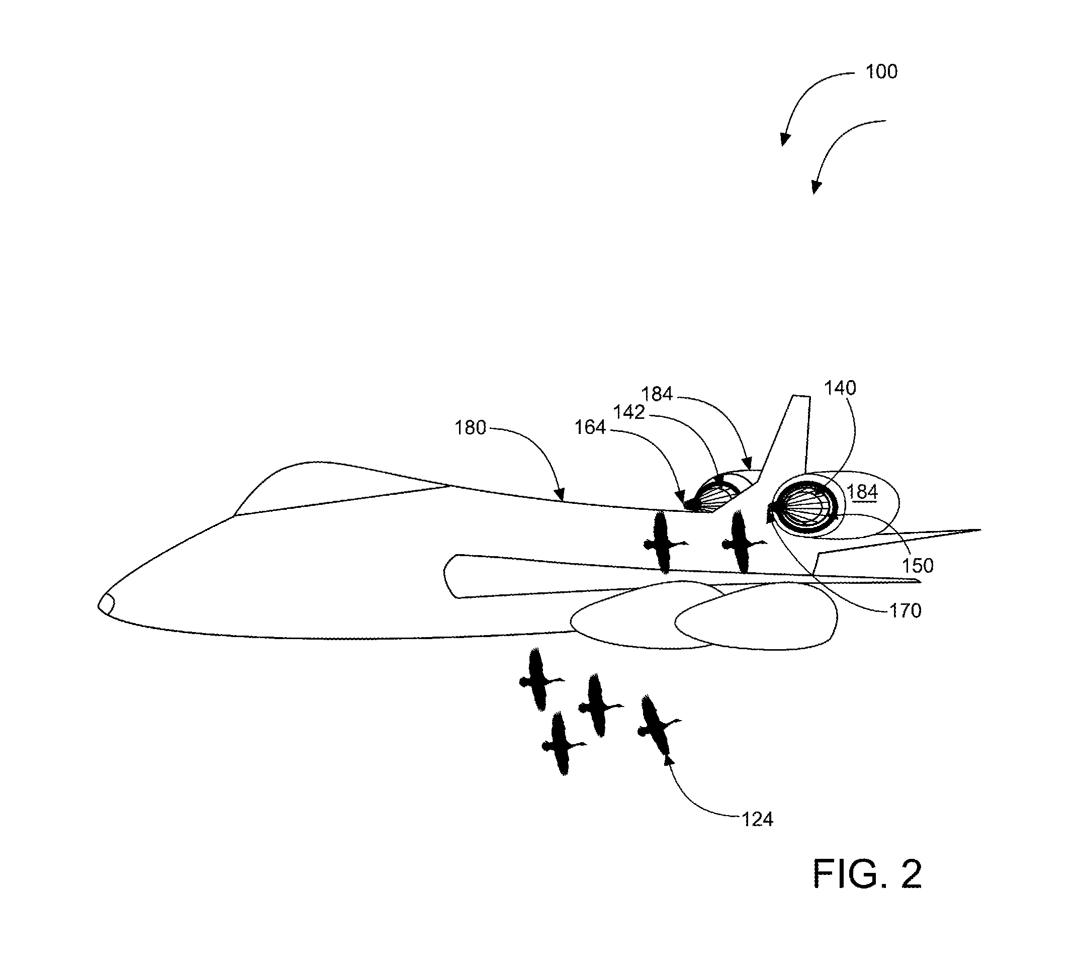
[0027]As discussed previously, a risk of engine damage exists when a foreign object's path intersects with that of an airplane. The foreign object may get pulled into the engine turbine from the tremendous force of the air being ‘sucked’ inwardly and may lead to serious damage to the engine. Such damage may result in a catastrophic airplane crash. This is a serious problem that plagues the aviation industry. The safety of an airplane engine during flight is of utmost concern and requires the ultimate standard of care, as modern technology permits, in protecting the integrity and stability of the aircraft and the lives of the passengers onboard. Further, it is of concern that birds...


PUM


Abstract

An aircraft system comprising a deflector assembly including, a base having mounting apertures; an inner ring concentrically positioned within an outer ring, the inner ring and the outer ring have an annulus defined therebetween via a base plate, a plurality of rods attached within the annulus and culminating at an apex creating a conical profile; and a forward-mounted cone-shaped deflecting member. The base plate comprises a through hole allowing airflow through the deflector assembly to supply an airplane engine. The aircraft safety device system further comprises at least one locking latch for removably securing the deflector assembly to a housing of the airplane engine. The aircraft safety device is mountable inside a lip of the housing of the airplane engine. Further, the aircraft safety device provides protection for airplane engines from air born animate and inanimate objects.

Description

CROSS-REFERENCE TO RELATED APPLICATION[0001]The present application is related to and claims priority from prior provisional application Ser. No. 61 / 416,334, filed Nov. 23, 2010, and Ser. No. 13 / 304,212, filed on Nov. 23, 2011, which applications are incorporated herein by reference.COPYRIGHT NOTICE[0002]A portion of the disclosure of this patent document contains material which is subject to copyright protection. The copyright owner has no objection to the facsimile reproduction by anyone of the patent document or the patent disclosure, as it appears in the Patent and Trademark Office patent file or records, but otherwise reserves all copyright rights whatsoever. 37 CFR 1.71(d).BACKGROUND OF THE INVENTION[0003]The following includes information that may be useful in understanding the present invention(s). It is not an admission that any of the information provided herein is prior art, or material, to the presently described or claimed inventions, or that any publication or document...

Claims


Application Information

Patent Timeline
Patent Type & Authority Applications(United States)
IPC IPC(8): B64D33/02
CPCB64D2033/022B64D33/02
Inventor JONES, RICHARDJONES, TERRELL
Owner JONES RICHARD
Learn More