Emission control device regeneration

a technology of emission control device and regeneration reaction, which is applied in the direction of electric control, machines/engines, mechanical equipment, etc., can solve the problems of reducing fuel economy, affecting fuel economy, and reducing fuel economy, so as to increase fuel economy and vehicle drivability

Active Publication Date: 2016-07-14
FORD GLOBAL TECH LLC
View PDF2 Cites 28 Cited by
  • Summary
  • Abstract
  • Description
  • Claims
  • Application Information

AI Technical Summary

Benefits of technology

[0009]In this way, DFSO initiated as part of active filter regeneration may be utilized to replenish oxygen stored in the emission control device, which may increase the frequency with which passive filter regene

Problems solved by technology

As particulate matter accumulates in a particulate filter, exhaust backpressure will increase, which can adversely affect fuel economy.
Supplying excess oxygen for a regeneration reaction in a spark-ignition may be difficult, however, as spark-ignition engines are typically operated under stoichiometric conditions.
While this may suf

Method used


Image

  • Emission control device regeneration
  • Emission control device regeneration
  • Emission control device regeneration

Examples


Embodiment Construction

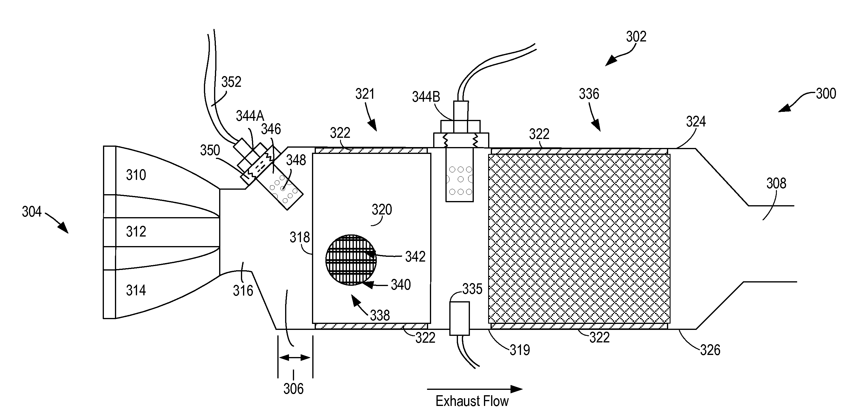
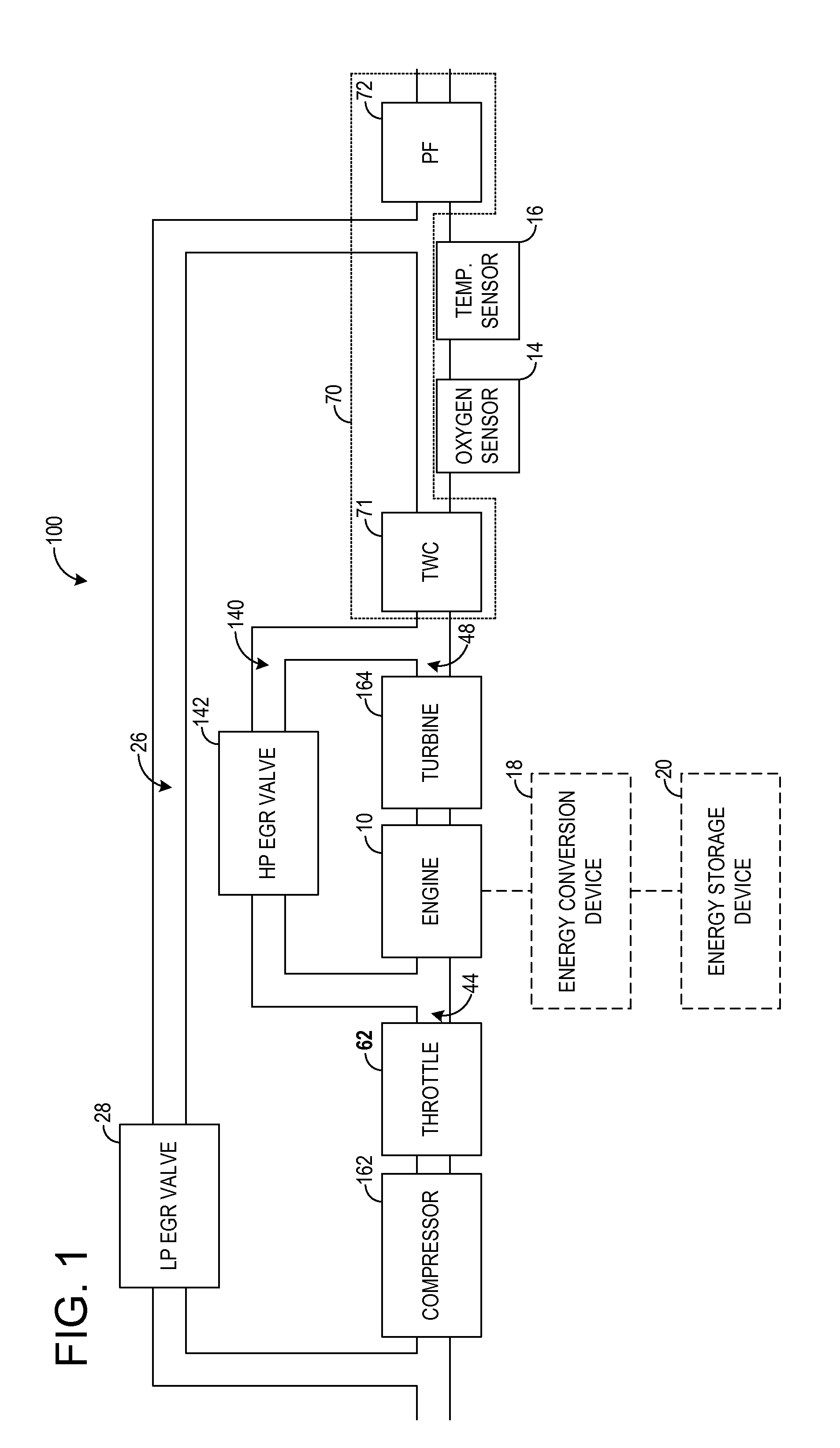
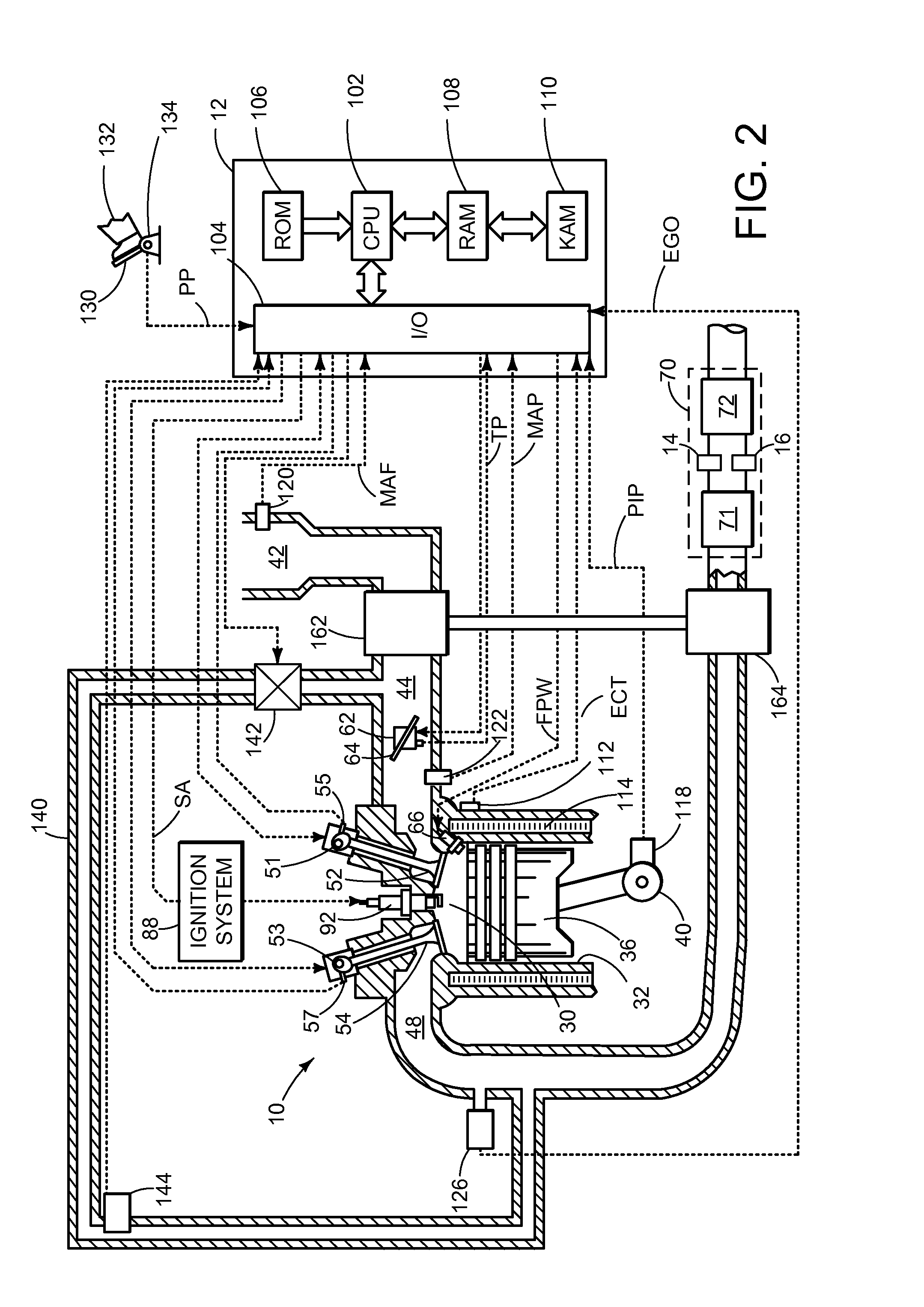
[0020]Various methods are provided for operating an emission control device. In one example, a method for an emission control device including a catalyst and a filter comprises passively regenerating the filter, and adjusting, via a controller, a duration of active regeneration of the filter based on an oxygen storage capacity of the emission control device. FIG. 1 is a block diagram of a system in a vehicle, FIG. 2 is a schematic view of an engine of a vehicle, FIG. 3A shows an example vehicle exhaust system including an emission control device, FIG. 3B shows a block diagram illustrating aspects of the vehicle exhaust system of FIG. 3A, FIG. 4A shows another example vehicle exhaust system including an emission control device, FIG. 4B shows a block diagram illustrating aspects of the vehicle exhaust system of FIG. 4A, FIG. 5 shows a flowchart illustrating a method of regenerating a particulate filter of an emission control device, and FIG. 6 shows a graph illustrating how filter reg...


PUM


Abstract

Various methods are provided for operating an emission control device. In one example, a method for an emission control device including a catalyst and a filter comprises passively regenerating the filter, and adjusting, via a controller, a duration of active regeneration of the filter based on an oxygen storage capacity of the emission control device.

Description

FIELD[0001]The field of the disclosure generally relates to emission control devices.BACKGROUND AND SUMMARY[0002]Some internal combustion engines employ a particulate filter in an exhaust system to trap particulate matter flowing through the exhaust system and thereby meet emission standards. A turbocharged, spark-ignition engine may employ a particle filter to trap soot, for example. As particulate matter accumulates in a particulate filter, exhaust backpressure will increase, which can adversely affect fuel economy. Accordingly, a particulate filter may be periodically regenerated by oxidizing stored particulate matter. A regeneration reaction requires oxygen and suitable temperature conditions. Supplying excess oxygen for a regeneration reaction in a spark-ignition may be difficult, however, as spark-ignition engines are typically operated under stoichiometric conditions.[0003]U.S. Patent Application No. 2011 / 0073088 discloses methods of regenerating a particulate filter in a spa...

Claims


Application Information

Patent Timeline
IPC IPC(8): F01N3/025F01N3/035
CPCF01N3/035F01N3/0253F01N3/023F01N3/0293F01N9/002F01N11/002F01N2550/04F01N2610/06F01N2900/1602F01N2900/1606F02D41/029F02D41/0295F02D2200/0802F02D2200/0814F02D2250/34F01N3/101F01N13/009F01N2560/025F01N2560/06F01N2900/0416F01N2900/1624F02D41/0235F02D41/024F02D41/123F02D2200/0812F02D2200/0816Y02A50/20Y02T10/12Y02T10/40F01N3/2073
Inventor LAMBERT, CHRISTINE KAYDOBSON, DOUGLAS ALLENWARNER, JAMES ROBERTPAKKO, JAMES DAVIDHEPBURN, JEFFREY SCOTT
Owner FORD GLOBAL TECH LLC
Why Eureka
Try Eureka