
Transmitter and Method for Substantially Reducing Dead Zones in an Inductive Contactless Mobile Payment System

a mobile payment system and transmitter technology, applied in the near field of read/write/interrogation/identification system, transformer/inductance magnetic core, instruments, etc., can solve the problems of one or more nulls, the mobile wallet application on smartphones and tablets has had difficulty interacting with existing merchant point of sale devices or other devices with msrs, and the millions of merchants have to replace in tim

Active Publication Date: 2016-07-14
SAMSUNG ELECTRONICS CO LTD
View PDF2 Cites 5 Cited by
  • Summary
  • Abstract
  • Description
  • Claims
  • Application Information

AI Technical Summary

Benefits of technology

The patent text describes a technique where inductors are placed in a way that the signal strength is stronger than the reader's detection limit, which helps to improve data reading.

Problems solved by technology

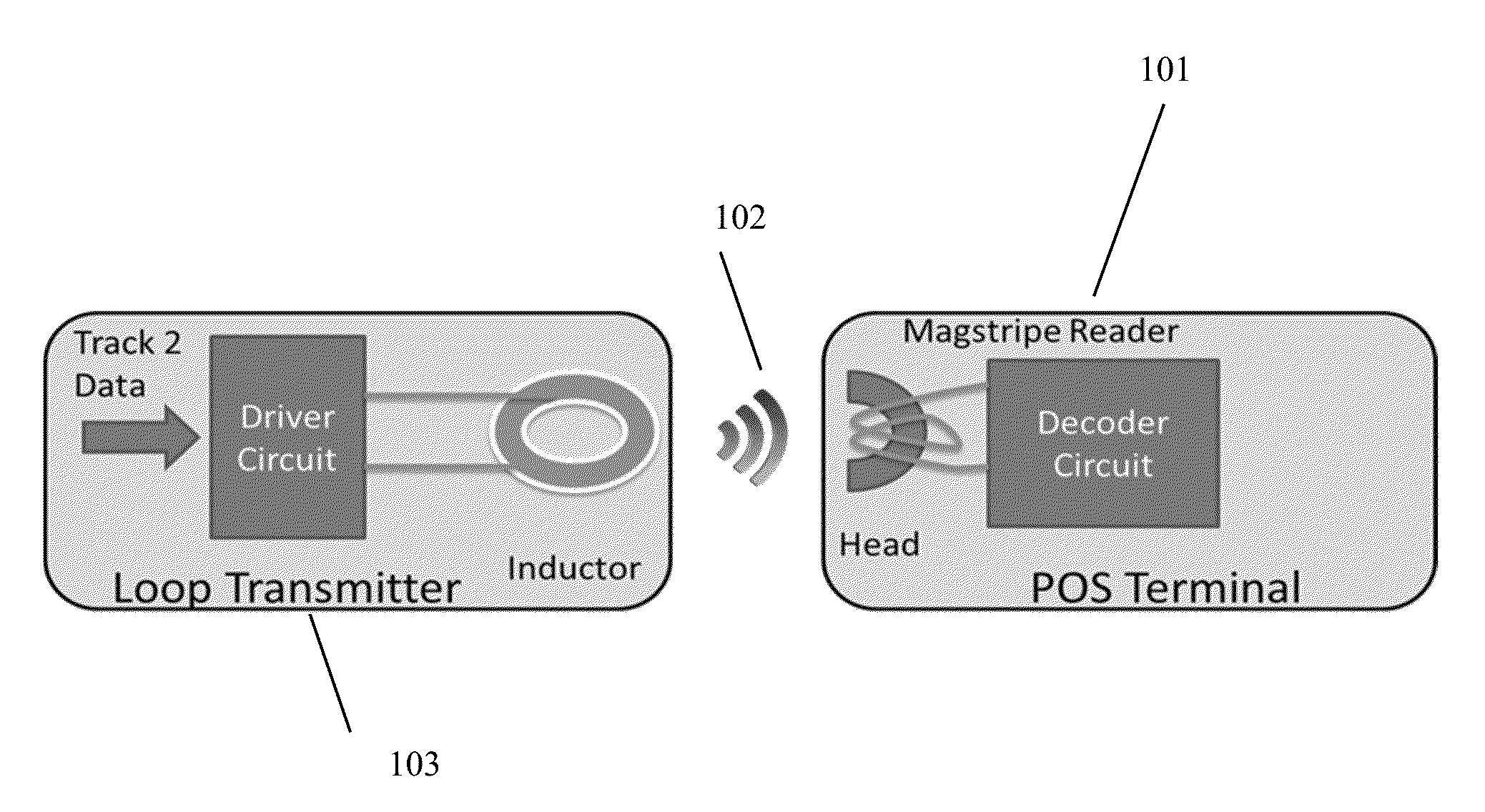
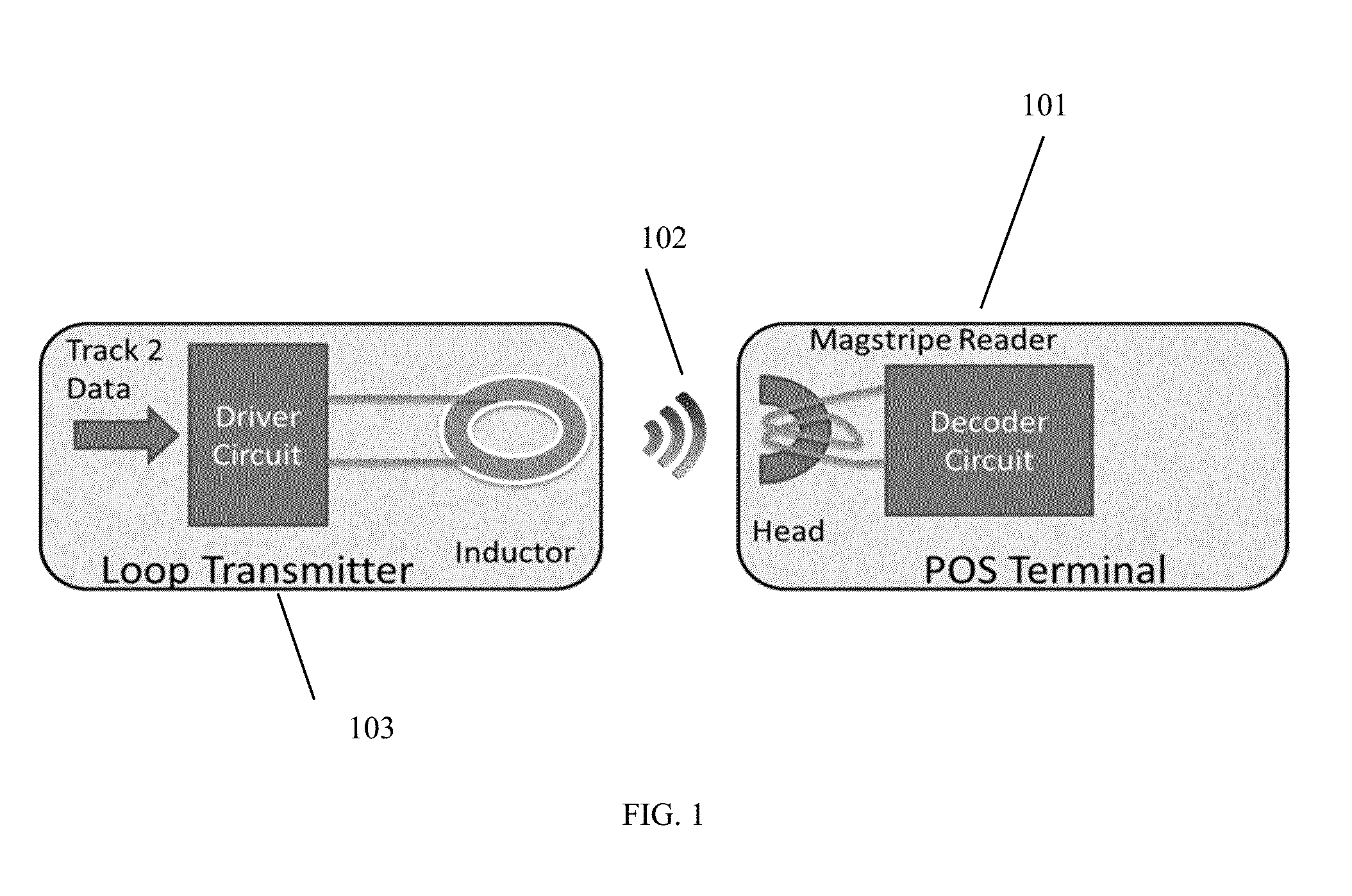
Mobile wallet applications on smartphones and tablets have had difficulty interacting with existing merchant point of sale (POS) devices or other devices with MSRs.
It would be expensive and would take time to replace the millions of merchant POS devices (or door locks) that only accept magnetic stripe cards, just to interact with NFC phones or other transmission means like barcodes.
However, in real life, inductors, including NFC inductors, do not have isotropic fields.
The overlapping field patterns of the MST transmitter inductor and the reader head inductor result in one or more nulls: narrow areas where no signal transfer takes place.
Nulls affect the reliability of card data transmissions.
While users quickly learn in which position their LoopPay device works best, some inconvenience and the need for two or three tries results at times. When MST is integrated into a smart-phone, which is larger than a LoopPay device, precise placement is less likely and therefore first-time MST transmission success rate suffers.

Method used


Image

  • Transmitter and Method for Substantially Reducing Dead Zones in an Inductive Contactless Mobile Payment System
  • Transmitter and Method for Substantially Reducing Dead Zones in an Inductive Contactless Mobile Payment System
  • Transmitter and Method for Substantially Reducing Dead Zones in an Inductive Contactless Mobile Payment System

Examples


Embodiment Construction

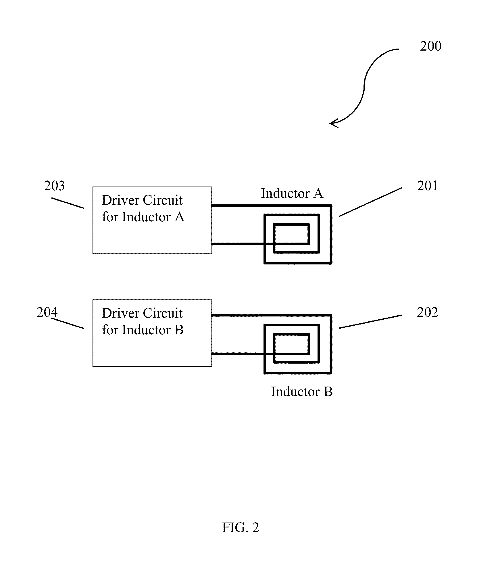
[0041]A transmitter 200 to generate a signal to be read by a reader is described. The transmitter 200 includes a driver circuit; and at least two inductors, 201 and 202, connected to the driver circuit 203 and 204, respectively. The driver circuit controls the current flow through the inductors and the current flows result in a magnetic fields. The magnetic fields include areas where the signal strength is below the detection limit of the reader for each of the inductors, 201 and 202, which forms at least one null region. Additionally, the inductors, 201 and 202, are positioned such that the null regions of the inductors do not overlap.

[0042]FIG. 2 shows a schematic of the transmitter 200 according to the present invention. Inductor A 201 and Inductor B 202 are driven by driver circuits A 203 and 204, respectively.

[0043]The voltages induced by a flat, horizontal inductor 301 into a typical POS terminal's card reader-head 302 from different relative positions along the card reader sw...


PUM

PropertyMeasurementUnit
distanceaaaaaaaaaa
current flowaaaaaaaaaa
signal strengthaaaaaaaaaa

Abstract

A transmitter to generate a signal to be read by a reader is described. The transmitter includes a driver circuit; and at least two inductors connected to the driver circuit. The driver circuit controls the current flow through the inductor and the current flow results in a signal such that the signal strength is above the detection limit of the reader for each of the inductors which may have at least one null region. Additionally, the inductors are positioned such that the null regions of the inductors do not overlap.

Description

RELATED APPLICATIONS[0001]This application claims the benefit of the earlier filing date of U.S. Patent Application No. 62 / 103,237, filed on Jan. 14, 2015, the contents of which are incorporated by reference herein in its entirety.BACKGROUND[0002]Transmission of magnetic stripe data has been done primarily by swiping a magnetic stripe card against a magnetic stripe reader (MSR) to enable payment, identification (ID), and access control functions. Mobile wallet applications on smartphones and tablets have had difficulty interacting with existing merchant point of sale (POS) devices or other devices with MSRs. Contactless reader enabled POS terminals (typically using, for example, an ISO-14443 standard) are not ubiquitous to accept contactless or near field communications (NFC) payments. It would be expensive and would take time to replace the millions of merchant POS devices (or door locks) that only accept magnetic stripe cards, just to interact with NFC phones or other transmission...

Claims


Application Information

Patent Timeline
Patent Type & Authority Applications(United States)
IPC IPC(8): G06Q20/34H01F1/34H01F27/24H04B5/48
CPCG06Q20/341H01F1/34H01F27/24H01F38/14H01F2038/143H04B5/77H04B5/24G07G1/00
Inventor WALLNER, GEORGE
Owner SAMSUNG ELECTRONICS CO LTD
Learn More