Capacitive micro-machined ultrasound transducer cell

a micro-machined ultrasound and transducer technology, applied in mechanical vibration separation, medical science, diagnostics, etc., can solve problems such as reducing the acoustic performance of the transducer, and achieve the effect of improving the propagation of acoustic waves

Active Publication Date: 2016-07-14
KONINKLJIJKE PHILIPS NV
View PDF12 Cites 12 Cited by
  • Summary
  • Abstract
  • Description
  • Claims
  • Application Information

AI Technical Summary

Benefits of technology

[0014]The choice of materials according to the invention, i.e. materials that exhibit an acoustic loss per millimeter for acoustic energy passing therethrough of less than 1.5 dB for energy of an acoustic frequency of 2 MHz and further exhibit an acoustic propagation velocity for acoustic energy passing therethrough which is in the range of 0.5 to 2.5 mm / microsecond, provides a superior coupling and propagation of the acoustic energy from the CMUT into the propagation medium. Compared to traditional RTV acoustic materials a minimal attenuation and frequency downshift are observed. The acoustical coupling of the acoustic lens to the membrane of the CMUT provides an optimal preservation of mechanical properties of the vibrating (moving) part and results in the optimal acoustic energy propagation.
[0019]The liquid and gel materials may exhibit an acoustic loss per millimeter for acoustic energy passing therethrough of less than 1.5 dB for energy of an acoustic frequency of 2 MHz and further exhibits an acoustic propagation velocity for acoustic energy passing therethrough which is in the range of 0.5 to 2.5 mm / microsecond. Their application as one of the additional layers of the acoustic lens provides an improved coupling and transfer of the acoustic energy from the transducer into the propagation medium (tissue, body, etc).
[0021]The layer of moisture barrier will provide a moisture protection, and the layer of conductive material may be adapted to act as a radio frequency (RF) shield. Essentially, the acoustic wave focusing layer provides desired focusing means for the acoustic wave propagation; and the durable exterior layer located as the outer patient-facing surface can provide a wear resistance, resistance to solvents or disinfectant solutions. The thickness of these layers shall be kept as low as possible, for example below 20 micrometer, for preserving the acoustic coupling of the elastomer, or liquid, or gel layers to the membrane of the CMUT cell.

Problems solved by technology

A drawback of the known CMUT transducer cell is that interactions between the CMUT membranes and the material of the lens 14 may reduce the acoustic performance of the transducer.

Method used


Image

  • Capacitive micro-machined ultrasound transducer cell
  • Capacitive micro-machined ultrasound transducer cell
  • Capacitive micro-machined ultrasound transducer cell

Examples


Embodiment Construction

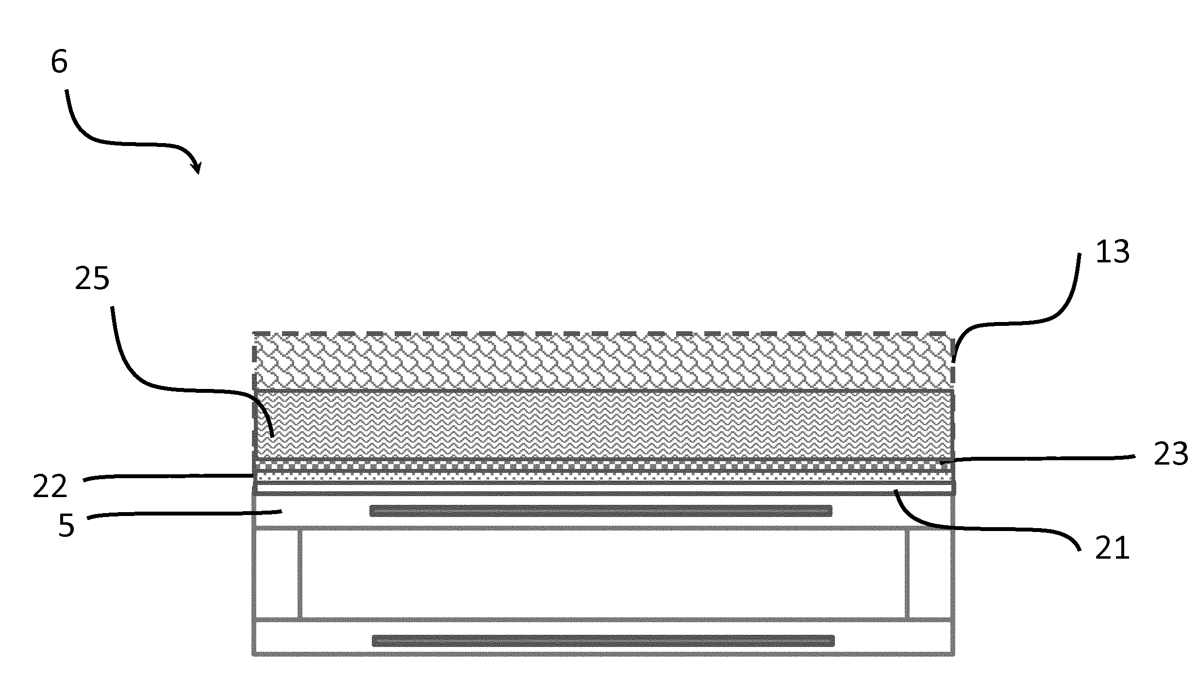
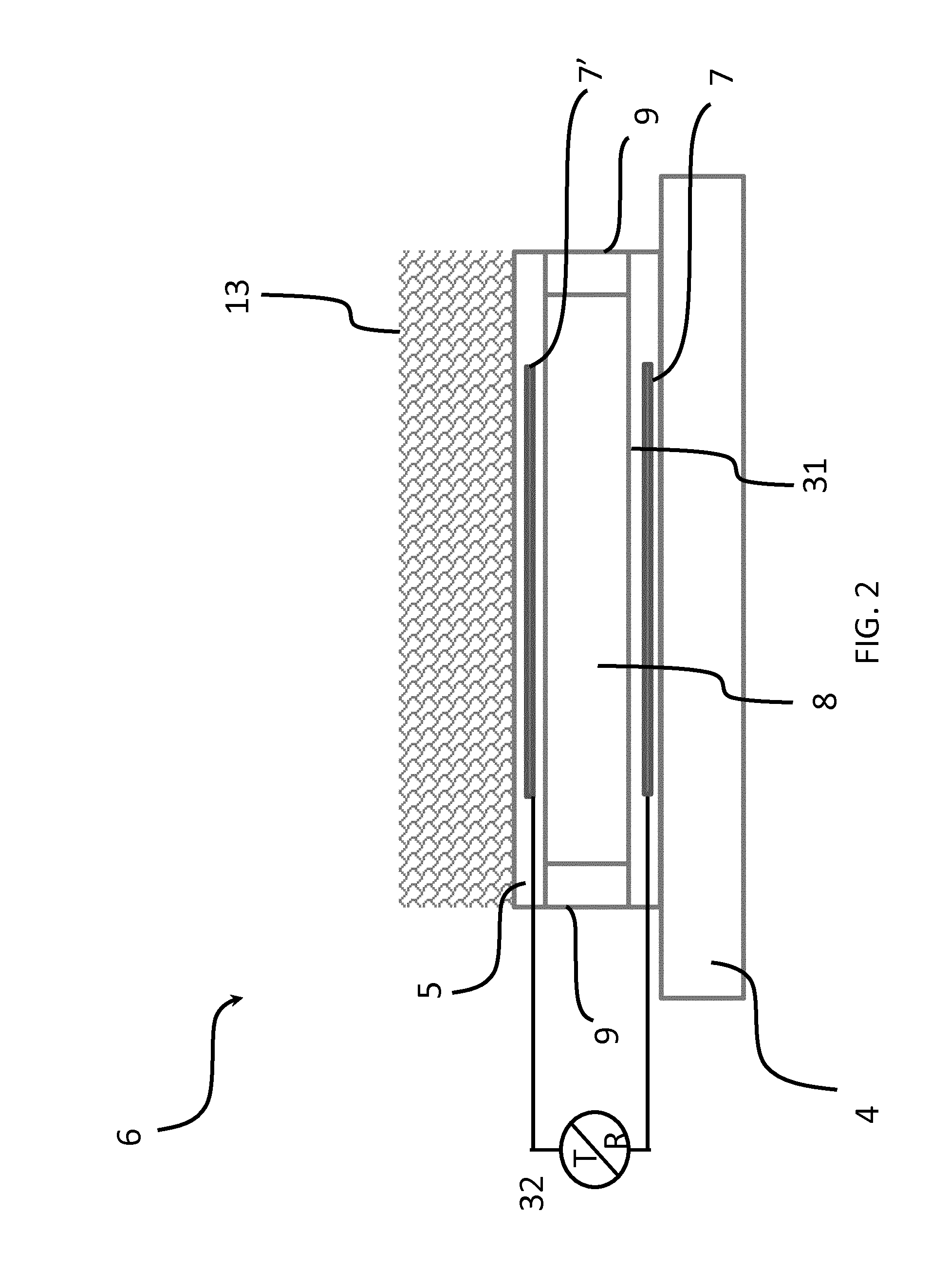
[0039]FIG. 2 shows schematically and exemplarily a CMUT cell in cross section according to the present invention. Such CMUT cell is typically fabricated on a substrate 4, such as a silicon wafer. The CMUT transducer of the ultrasound system may comprise one or more CMUT cells 6. The CMUT cells may be either individually activated or in combination with each other. The individual cells can have round, rectangular, hexagon or other peripheral shapes.

[0040]Each CMUT cell has at least a pair of electrodes 7′ and 7 separated by a cavity 8. The cavity 8 is formed in between a membrane 5 that is suspended over a cell floor 31. The membrane 5 may be made of silicon nitride and is adapted to move or vibrate. It can be suspended over the cell floor 31 through a plurality of supporting portions 9 (in FIG. 2 two supporting portions 9 are shown). The electrodes 7, 7′ are made of electrically conductive material, such as metal. The bottom electrodes 7 may be embedded in the floor of the cell 31, ...


PUM


Abstract

The invention relates to a capacitive micro-machined ultrasound transducer (CMUT) cell (6) comprising a cell floor (31) having a first electrode (7); a cell membrane (5) having a second electrode (7′) which opposes the first electrode and vibrates during transmission or reception of acoustic energy; a transmitter / receiver coupled to the first and second electrodes which causes the cell membrane to vibrate at an acoustic frequency and / or receives signals at an acoustic frequency; and an acoustic lens (13), overlaying the cell membrane, and having an inner surface opposing the cell membrane and an outer, patient-facing surface. According to the present invention the acoustic lens comprises at least one layer of a material selected from the group of: polybudatiene, polyether block amide (PEBAX), polydimethylsiloxane (PDMS) and buthylrubber.

Description

FIELD OF THE INVENTION[0001]The invention relates to a capacitive micro-machined ultrasound transducer (CMUT) cell comprising a cell floor having a first electrode; a cell membrane having a second electrode which opposes the first electrode and vibrates during transmission or reception of acoustic energy; a transmitter / receiver coupled to the first and second electrodes which causes the cell membrane to vibrate at an acoustic frequency and / or receives signals at an acoustic frequency; and an acoustic lens, overlaying the cell membrane, and having an inner surface opposing the cell membrane and an outer, patient-facing surface.[0002]The invention further relates to an ultrasonic imaging system comprising such a cell.BACKGROUND OF THE INVENTION[0003]Central to any ultrasound (imaging) system is the ultrasound transducer which converts electrical energy in acoustic energy and back. Recent progress in semiconductor technology resulted in the development of capacitive micro-machined ultr...

Claims


Application Information

Patent Timeline
Patent Type & Authority Applications(United States)
IPC IPC(8): G10K11/00A61B8/00
CPCA61B8/4494G10K11/002B06B1/0292
Inventor BROCK-FISHER, GEORGE ANTHONYDAVIDSEN, RICHARD EDWARDHERICKHOFF, CARL DEANMARCELIS, BOUTSUDOL, WOJTEKSONG, JUNHO
Owner KONINKLJIJKE PHILIPS NV
Why Eureka
Try Eureka