

Spark plug
- Summary
- Abstract
- Description
- Claims
- Application Information
AI Technical Summary
Benefits of technology
Problems solved by technology
Method used
Image

Examples
first embodiment
A. First Embodiment
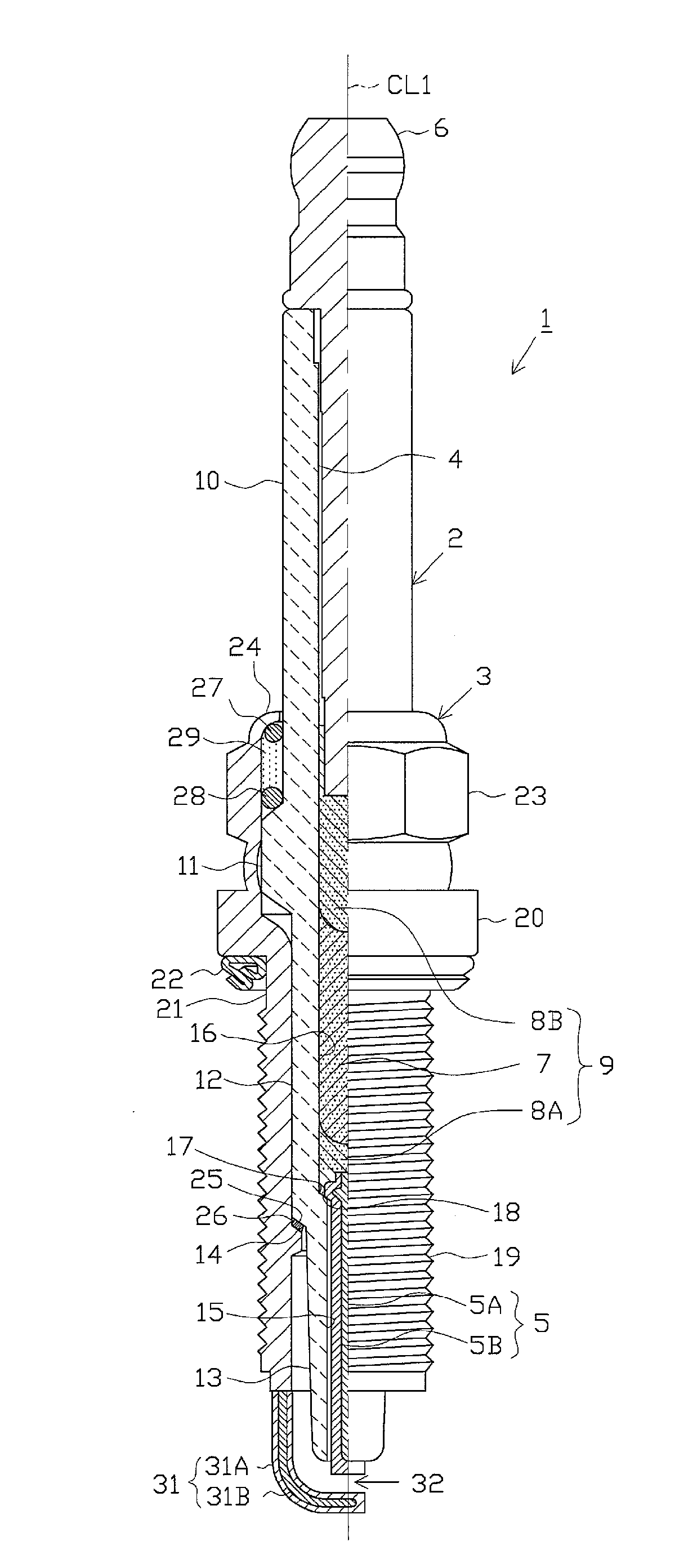
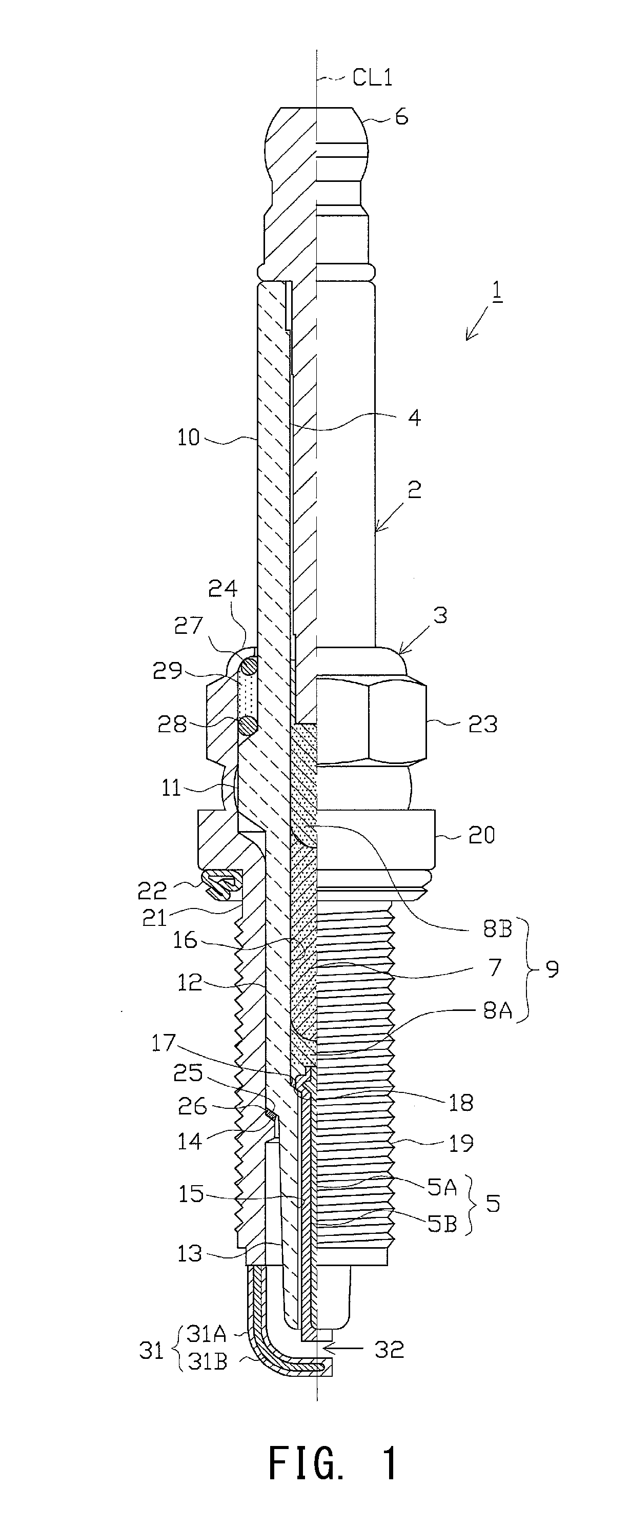
[0028]An embodiment of the present invention will next be described with reference to the drawings. FIG. 1 is a partially cutaway front view showing a spark plug 1. In FIG. 1, the direction of an axial line CL1 of the spark plug 1 corresponds to the vertical direction of the drawing, and, in the following description, the lower side is referred to as the forward side of the spark plug 1, and the upper side is referred to as the rear side.
[0029]The spark plug 1 includes a ceramic insulator 2, which is a tubular insulator, and a metallic shell 3.
[0030]The ceramic insulator 2 is, as well known, formed from alumina or the like by firing and, as viewed externally, includes a rear trunk portion 10 formed at its rear side; a large-diameter portion 11 located forward of the rear trunk portion 10 and protruding radially outward; an intermediate trunk portion 12 located forward of the large-diameter portion 11 and being smaller in diameter than the large-diameter portion 11...
second embodiment
B. Second Embodiment
[0107]FIG. 4 is a sectional view of an example spark plug according to a second embodiment of the present invention. The illustrated line CL indicates the center axis of a spark plug 100. The illustrated section is a section which contains the center axis CL. Hereinafter, the center axis CL may also be called the “axial line CL,” and a direction in parallel with the center axis CL may also be called the “axial direction.” A radial direction of a circle centered on the center axis CL may also be called the “radial direction,” and a circumferential direction of a circle centered on the center axis CL may also be called the “circumferential direction.” Regarding a direction in parallel with the center axis CL, a downward direction in FIG. 4 may also be called the “forward direction D1,” and an upward direction may also be called the “rearward direction D1r.” The forward direction D1 is directed toward electrodes 120 and 130 from a metal terminal member 140, which wi...
PUM
 Abstract
Description
Claims
Application Information