

LED tube adapted for use with electronic ballast or ac mains and controlling method thereof
- Summary
- Abstract
- Description
- Claims
- Application Information
AI Technical Summary
Benefits of technology
Problems solved by technology
Method used
Image

Examples
embodiment 1
[0043]2. The LED tube , wherein the first and the second rectifier circuits are a first and a second bridge rectifier circuits respectively, and each of the first and the second bridge rectifier circuits has one of a first instance of four fast diodes and a second instance of four super fast diodes.
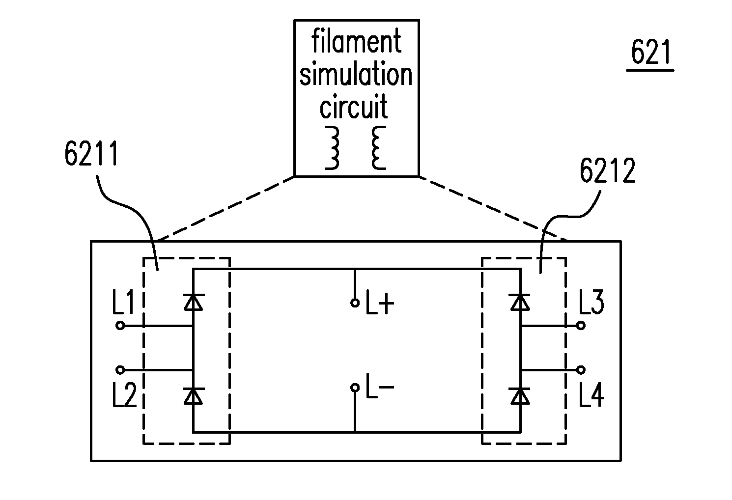
[0044]3. The LED tube according to Embodiment 1 or 2, further comprising a fluorescent lamp tube simulation circuit, wherein the filament simulation circuit further includes a first resistor having a resistance less than 5 KΩ and a second resistor having a resistance less than 5 KΩ, the first and the second bridge rectifier circuits both include two input terminals and a first and a second output terminals, the first resistor is electrically connected to the two input terminals of the first bridge rectifier circuit in parallel, the second resistor is electrically connected to the two input terminals of the second bridge rectifier circuit in parallel, the fluorescent lamp tube simulation c...
embodiment 11
[0057]12. The LED tube , wherein each of the plurality of LEDs is electrically connected to another one in one of two states being in series and in parallel, the lamp tube voltage simulation circuit is one of a thyristor element and a semiconductor switch element, and the lamp tube voltage simulation circuit is one selected from a group consisting of a DIAC, an SUS, an SIDAC, an SBS, an ASBS, an SAS, a Zener, a MOSFET, and a BJT.
[0058]13. The LED tube according to Embodiment 11 or 12, wherein the filament simulation circuit and the fluorescent lamp tube simulation circuit form a simulation circuit, the electronic ballast operates under a specific operation mode, and the simulation circuit responds to the specific operation mode.
[0059]14. The LED tube according to any one of the above-mentioned Embodiments, wherein the specific operation mode includes a resistance detection mode used to detect a resistance of a filament of an existing fluorescent lamp tube, and a lamp tube voltage de...
embodiment 15
[0063]16. The controlling method , wherein the specific operation mode includes a resistance detection mode and a lamp tube voltage detection mode, and the simulation circuit includes a filament simulation circuit, and a fluorescent lamp tube simulation circuit having a lamp tube voltage simulation circuit and a plurality of LEDs electrically connected to one another in one of two states being in series and in parallel, further comprising:[0064]causing the filament simulation circuit to provide a simulation datum of the resistance of the filament and to respond to the resistance detection mode accordingly so as to present a first status showing that the resistance of the filament is normal;[0065]causing the fluorescent lamp tube simulation circuit to use the plurality of LEDs to provide a stable lamp tube voltage;[0066]causing the lamp tube voltage simulation circuit to provide a starting high voltage for the lamp tube; and[0067]responding to the lamp tube voltage detection mode acc...
PUM
 Abstract
Description
Claims
Application Information