Modular furniture assembly with dual coupling mechanisms

a technology of coupling mechanism and modular furniture, which is applied in the direction of convertible stools, magnetic bodies, chairs, etc., can solve the problems of inconvenient connection between modular furniture pieces, requiring too many steps, and many traditional couches and other furniture items cannot be moved into tight areas of homes or apartment complexes, so as to reduce, minimize or prevent tenting of fabric or other covers, reduce or eliminate slack within the tethered construction chain

Active Publication Date: 2016-07-21
THE LOVESAC CORP
View PDF3 Cites 27 Cited by
  • Summary
  • Abstract
  • Description
  • Claims
  • Application Information

AI Technical Summary

Benefits of technology

[0009]Providing dual coupling mechanisms where one mechanism couples one edge (e.g. the top), while another mechanism couples another edge (e.g., opposite from the first, e.g., the bottom) provides for a very strong connection between the two members, even while using coupling materials typically regarded as weak, temporary, or transient. Such is highly advantageous.
[0012]Another aspect of the present invention relates to a modular furniture assembly including a first member and a second member. Either or both of the first member and the second member may include a fabric or other cover over a body (e.g., which may optionally be foam), where the body includes a rigid core. A coupling mechanism that is a magnetically attractive coupling mechanism and / or a mechanical coupling mechanism may be provided for selectively, removably coupling the first member to the second member. The coupling mechanism may include anti-tenting characteristics to prevent the fabric or other cover material of the first member and / or the second member from “tenting” as a first member and second member are pulled apart from one another. For example, the coupling mechanism may include a first member portion on or within the first member, and a second member portion disposed on or within the second member. The first member portion may be tethered to the rigid core of the first member. The second member portion may be tethered to the rigid core of the second member. Such a rigid core may include a rigid board or other relatively inflexible structure of the body that can serve as an anchor to which the coupling mechanism portions may be tethered. Such tethering reduces, minimizes or prevents tenting of the fabric or other cover(s) as the first member portion (e.g., a magnet, attracted member, VELCRO panel, etc.) is pulled relative to the remainder of the first member, or as the second member portion (e.g., a magnet, attracted member, VELCRO panel, etc.) is pulled relative to the remainder of the second member.
[0013]For example, where the coupling mechanism includes a magnetically attractive coupling mechanism, the first member portion of the coupling mechanism (e.g., a magnet or attracted member) may be tethered to the rigid board at the core of the first member (e.g., a base member). Where the coupling mechanism includes a mechanical coupling mechanism, the transverse member portion of the coupling mechanism, e.g., a VELCRO tab, which may extend laterally from a mid-section of the second member (e.g., a transverse member) may be tethered to a rigid board or other relatively inflexible member at the core of the second member. In either case, such tethering may reduce, minimize, or prevent tenting in the surrounding fabric or other cover that would otherwise occur without such tethering.
[0014]Such anti-tenting characteristics may be provided in various other manners where the coupling mechanism (e.g., magnetic, mechanical, or otherwise) is tethered to some structure (e.g., a rigid structure) of the base member or transverse member, the rigid board core merely being an example of such. Such tethering mechanisms reduce or eliminate slack within the tethered construction chain, anchoring a desired structure (e.g., the fabric cover in the vicinity of a coupling mechanism that may otherwise pull, stretch, and / or “tent” the cover) in order to minimize or reduce such characteristics. Other specific mechanisms by which tethering of the coupling components may be provided so as to reduce tenting of a fabric or other cover material will be apparent to one of skill in the art in light of the present disclosure.
[0019]In an embodiment, in addition to a magnetically attractive coupling mechanism (which is helpful in aiding the first member and second member(s) in orienting and aligning themselves in a proper orientation for coupling), a mechanical coupling mechanism is also provided. For example, one of the members (e.g., the transvers member(s)) may include a VELCRO tab (e.g., including the hook portion of the VELCRO), which extends laterally from member (e.g., the transverse member). This tab can be stretched over a surface of the other member (e.g., the base member) to which it becomes engaged. For example, a VELCRO tab of the transverse member can engage a top surface of the base member (which may include the loop portion of the VELCRO), securing the base member and transverse member to one another. Of course, the locations of the hook and loop (or other mechanical coupling portions) can be switched with one another. Such a dual coupling mechanism is particularly sturdy, reliable, and beneficial. Because no hard, rigid connections are required on the exterior of the members, it also preserves the soft characteristics of a fabric over foam construction of the base members and transverse members, should such be provided.

Problems solved by technology

In addition, many traditional couches and other furniture items cannot be moved into tight areas of a home or apartment complex, including, for example, basements, narrow hallways, or upstairs rooms.
However, the connections between modular assembly furniture pieces are often inconvenient, requiring too many steps for a convenient coupling of the various pieces together.
In some, the connections are not sufficiently robust, allowing the pieces to separate when such separation is not desired.

Method used


Image

  • Modular furniture assembly with dual coupling mechanisms
  • Modular furniture assembly with dual coupling mechanisms
  • Modular furniture assembly with dual coupling mechanisms

Examples


Embodiment Construction

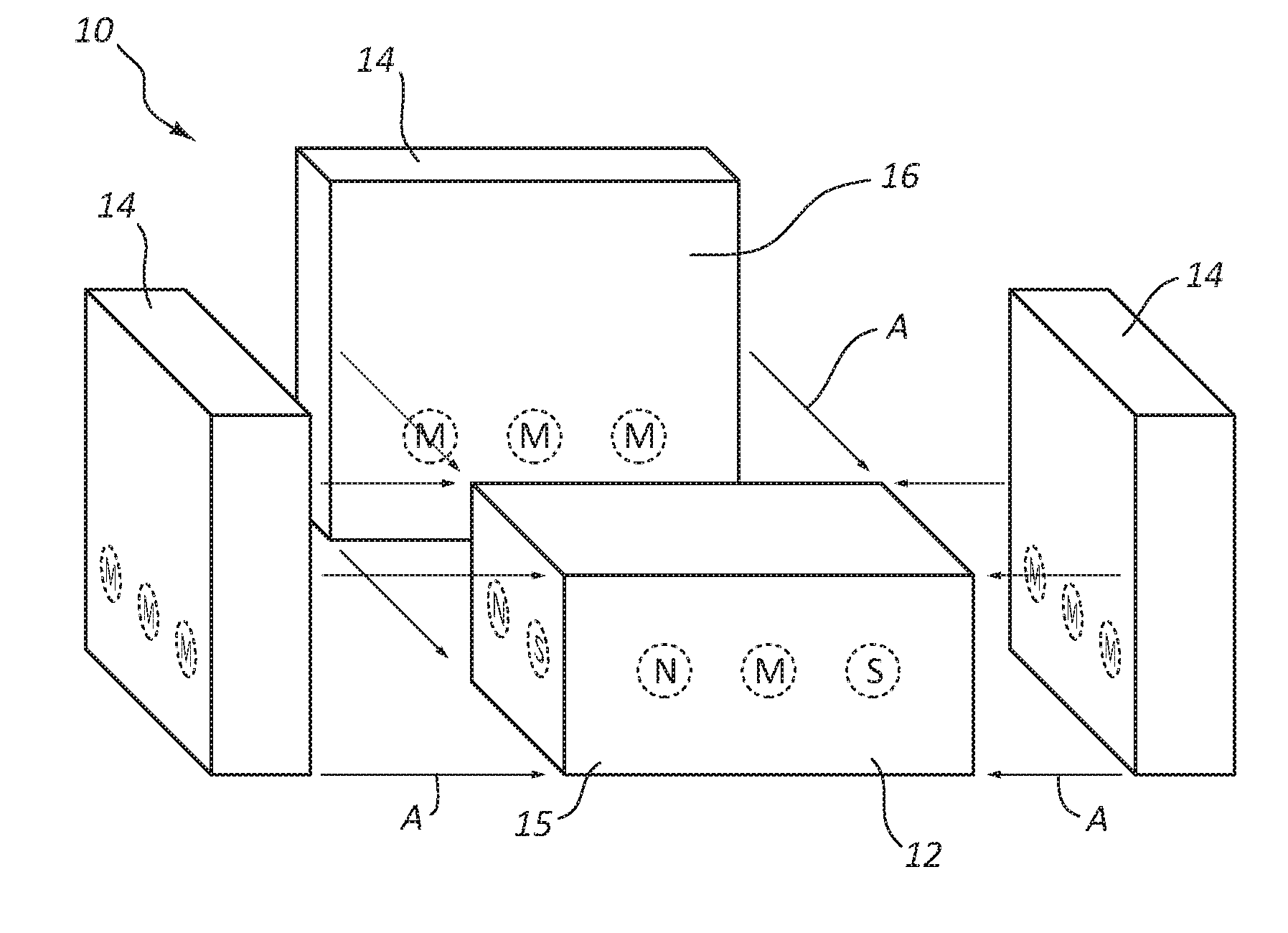
[0063]FIGS. 1A-5D are schematic representations of a modular furniture assembly with a magnetically attractive coupling assembly (also referred to herein as a magnetic coupling assembly), illustrating how the magnets and / or attracted members may be arranged so as to allow selective, removable coupling of the various members in variously configured modular furniture assemblies.

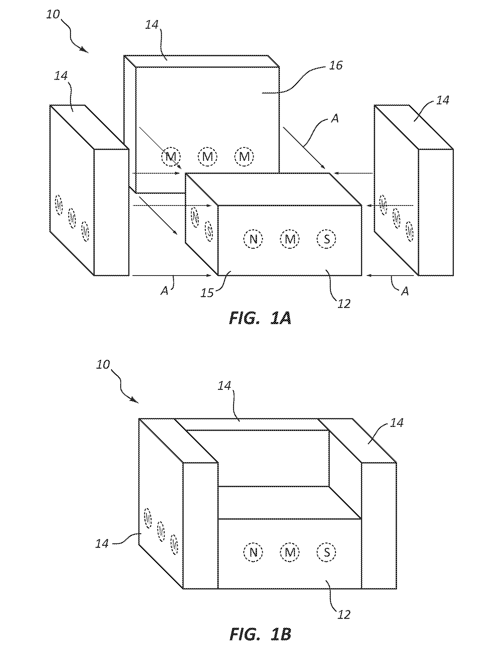
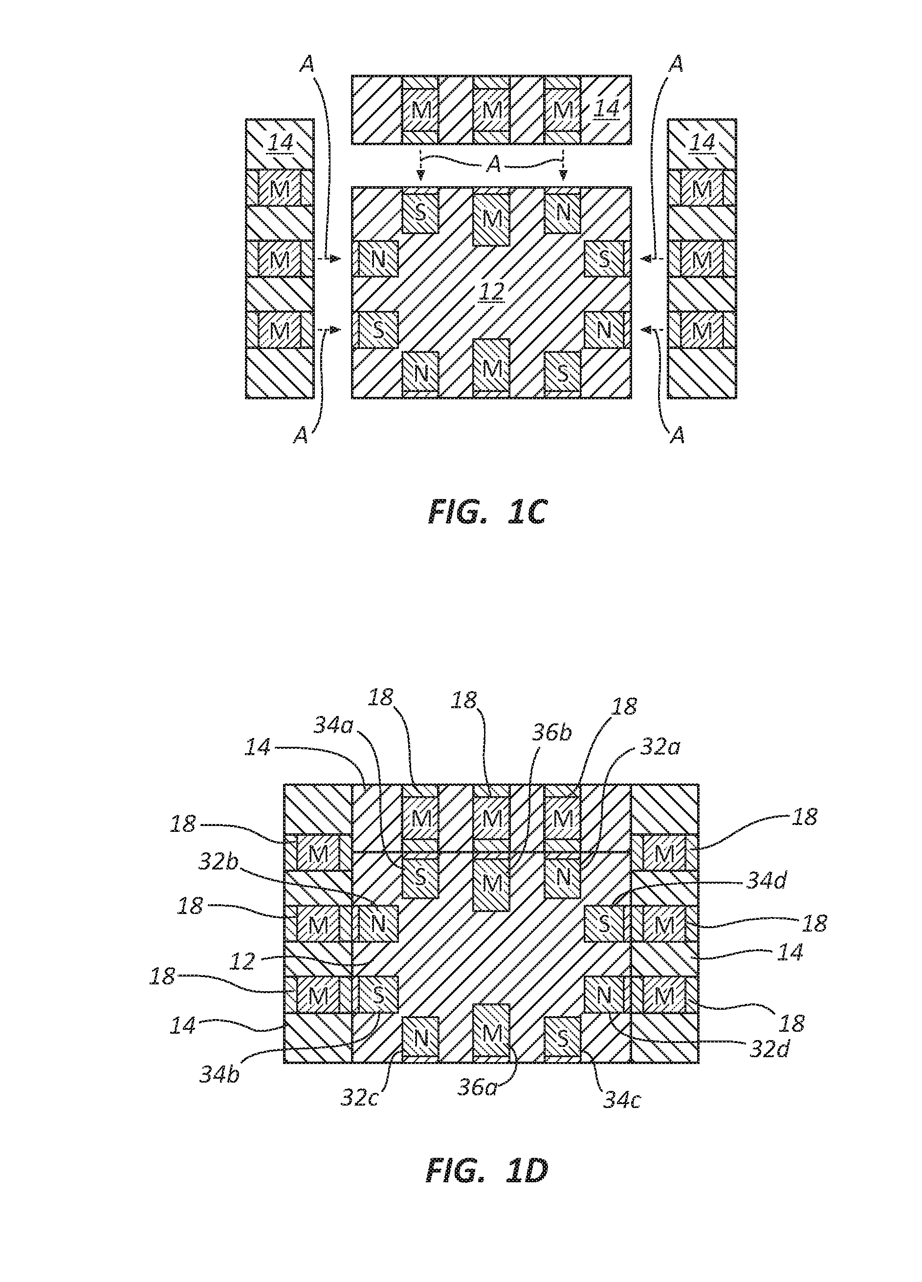
[0064]FIG. 1A shows an assembly 10 with a magnetic coupling assembly, while FIG. 1B is a view of the furniture assembly 10 of FIG. 1A in an assembled configuration. FIGS. 1C and 1D show possible positions of magnets and / or attracted members in the base member and transverse members for the assembly 10 of FIGS. 1A and 1B.

[0065]Modular furniture assembly 10 comprises a base member 12 and three transverse members 14 that are selectively, removably coupled by a magnetic coupling assembly to base member 12. The magnetic coupling assembly is comprised of at least one magnet and at least one attracted member, e.g., an...


PUM


Abstract

A modular furniture assembly comprising first and second members (e.g., base and transverse member) may have convenient dual coupling mechanisms, for example, a magnetic coupling mechanism and a mechanical (e.g., hook and loop) coupling mechanism. The first member and / or second member may include a fabric or other cover over a foam or other body (e.g., fabric over foam, or other cover over a skeleton). Either or both members may include a rigid core (e.g., a board, skeleton, etc.). The coupling mechanisms may be such as to not detract from any soft, cushioned characteristics of a fabric over foam construction, if such is provided. The coupling structure in the first member and / or the second member may be tethered to the rigid core of the particular member to reduce tenting of the fabric or other cover of the first member and / or the second member as the tethered coupling structure is pulled.

Description

1. CROSS-REFERENCE TO RELATED APPLICATIONS[0001]This application claims priority to and the benefit of U.S. provisional patent application No. 62 / 210,238 filed Aug. 26, 2015, entitled MODULAR FURNITURE ASSEMBLY WITH MAGNETIC COUPLING. This application is also a continuation-in-part of U.S. patent application Ser. No. 12 / 967,671, filed Dec. 14, 2010, entitled MODULAR FURNITURE ASSEMBLY AND DISPLAY KIT WITH MAGNETIC COUPLING ASSEMBLY, which claims priority to and the benefit of U.S. provisional patent application No. 61 / 413,125, filed Nov. 12, 2010, entitled MODULAR FURNITURE ASSEMBLY AND DISPLAY KIT WITH MAGNETIC COUPLING ASSEMBLY. Each of the foregoing applications is incorporated herein, in its entirety, by reference.2. FIELD OF THE INVENTION[0002]This invention is in the field of modular furniture.3. BACKGROUND[0003]Modular furniture is useful in a variety of settings. Consumers eager to have options for arranging furniture in multiple ways can purchase modular furniture which wil...

Claims


Application Information

Patent Timeline
Patent Type & Authority Applications(United States)
IPC IPC(8): A47C4/02F16B12/00F16B1/00
CPCA47C4/028F16B1/00F16B2001/0028F16B2001/0035F16B12/00A47C31/003A47B87/00A47C13/005H01F7/0252Y10T24/32F16B2200/81F16B2200/83
Inventor NELSON, SHAWN D.UNDERWOOD, DAVID M.PEARSON, SPENCERKOSTEK, CHELSEAKUCHLER, BRIAN
Owner THE LOVESAC CORP
Why Eureka
Try Eureka