Blade fastening device having cuttign fluid guide grooves on a blade

a blade and fluid guide technology, applied in the direction of chucks, manufacturing tools, transportation and packaging, etc., can solve the problems of relatively weak spraying strength and significant reduction of so as to reduce the temperature, maintain the structural strength of the blade, and facilitate the cutting operation

Inactive Publication Date: 2016-07-21
XPOLE PRECISION TOOLS
View PDF30 Cites 12 Cited by
  • Summary
  • Abstract
  • Description
  • Claims
  • Application Information

AI Technical Summary

Benefits of technology

[0011]It is envisaged by the invention that the blade can guide cutting fluid to an object being machined via the at least one groove so as to clear swarf left at a cutting site and decrease temperature at the cutting site. Further, the cutting operation is made easy. Furthermore, the structural strength of the blade can be maintained.

Problems solved by technology

However, the spraying strength is relatively weak due to the axial location of the channel 70.
However, the holes may significantly decrease the structural strength of the blade 80.

Method used


Image

  • Blade fastening device having cuttign fluid guide grooves on a blade
  • Blade fastening device having cuttign fluid guide grooves on a blade
  • Blade fastening device having cuttign fluid guide grooves on a blade

Examples


Embodiment Construction

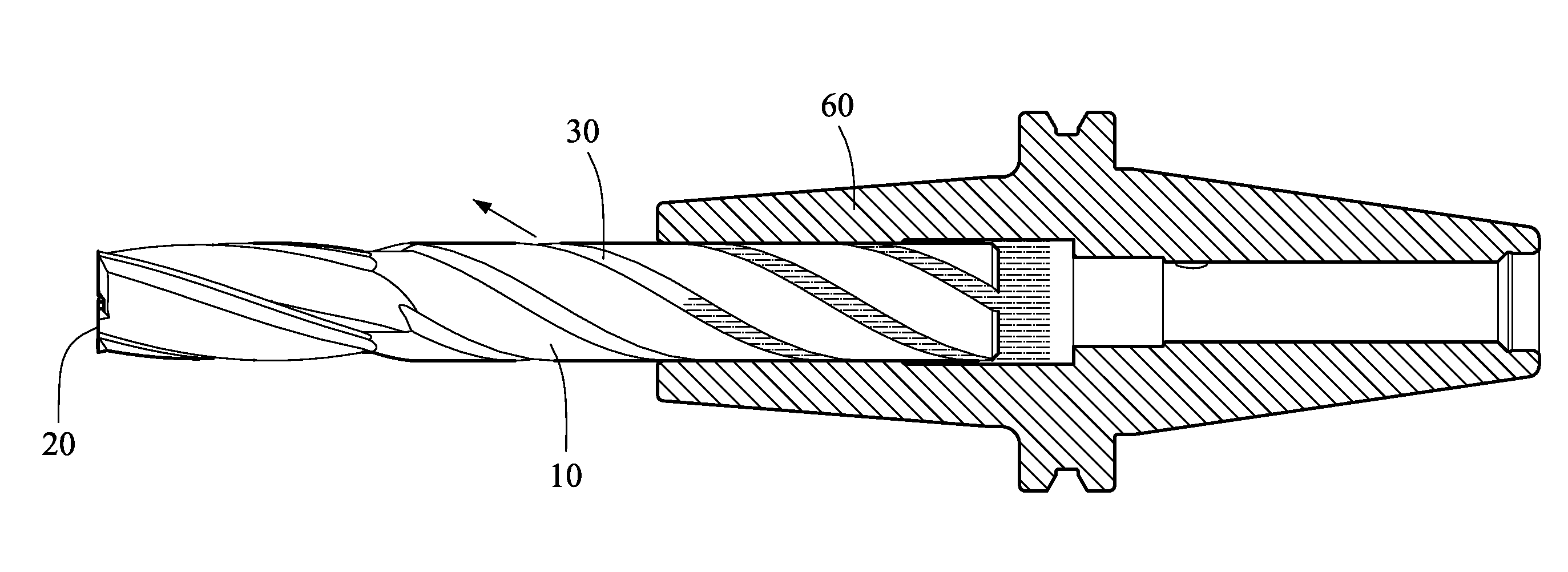
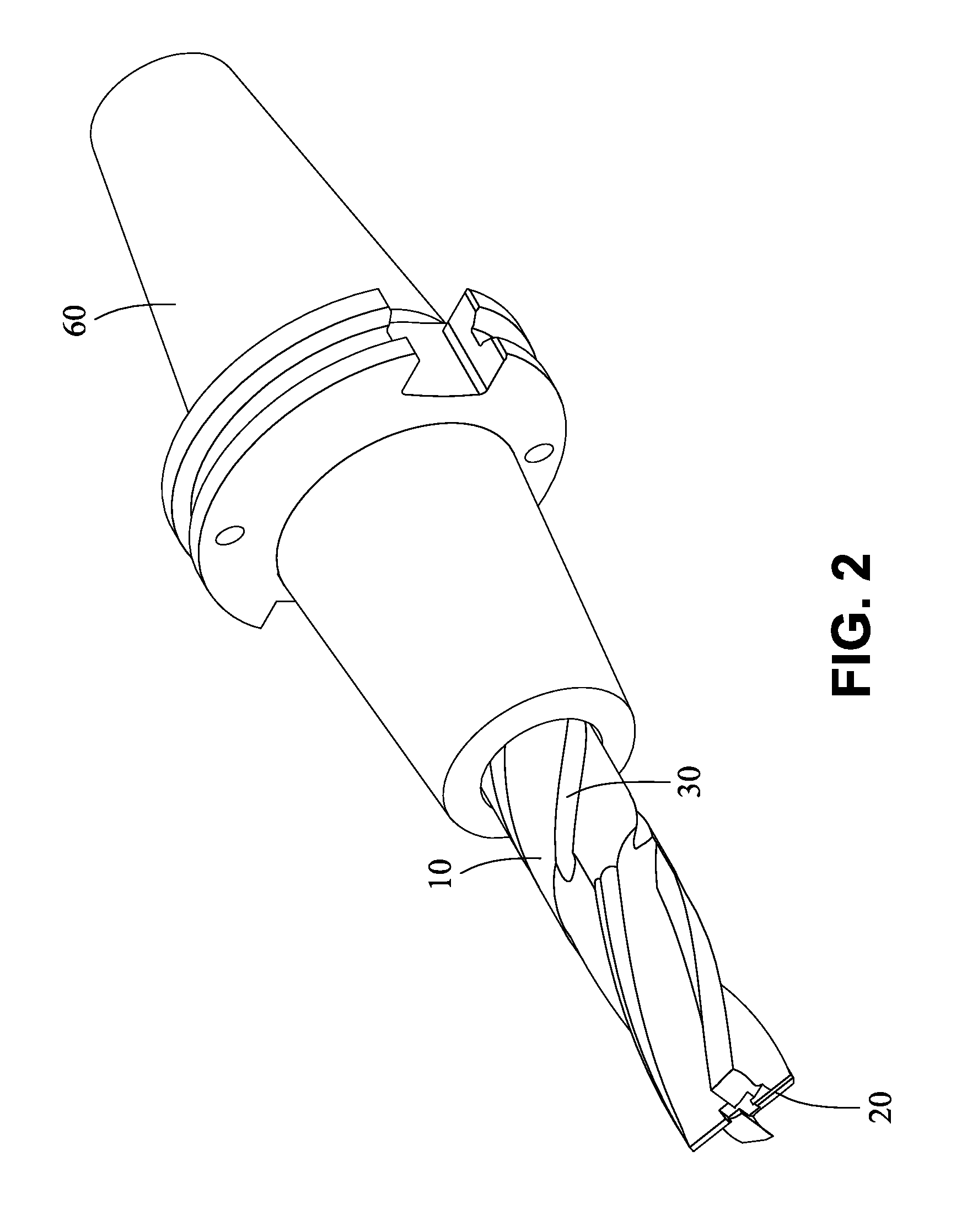
[0019]Referring to FIGS. 2 to 4, a blade fastening device incorporating a first preferred embodiment of blade in accordance with the invention is shown. A blade seat 60 is secured to a body 10 of the blade by fastening a portion of the body 10 therein. A forward portion of the body 10 is exposed. The body 10 is cylindrical and comprises the following components as discussed in detail below.

[0020]A machining point 20 is provided at a forward end of the body 10. The machining point 20 is configured as a tool for machining on an object. A plurality of helical grooves 30 are formed on a surface of the body 10. The helical grooves 30 extend from a rear end of the body 10 to the machining point 20. Cutting fluid can flow from rear ends of the helical grooves 30 to forward ends thereof for clearing swarf left at a cutting site and decreasing temperature at the cutting site.

[0021]Referring to FIG. 5, a blade fastening device incorporating a second preferred embodiment of blade in accordance...


PUM

PropertyMeasurementUnit
strengthaaaaaaaaaa
structural strengthaaaaaaaaaa
temperatureaaaaaaaaaa

Abstract

A blade for a blade fastening device is provided with a body having a first end fastened in a blade seat and a second end extending out of the blade seat; a machining point formed at the second end of the body for machining an object being machined; and at least one cutting fluid groove formed on a surface of the body and extending from the second end of the body to the machining point. The blade can guide cutting fluid to an object being machined via the at least one groove so as to clear swarf left at a cutting site and decrease temperature at the cutting site. Further, the structural strength of the blade can be maintained.

Description

BACKGROUND OF THE INVENTION[0001]1. Field of the Invention The invention relates to blade fastening devices and more particularly to a blade fastening device having grooves on a surface of a blade for guiding cutting fluid to an object being machined at a cutting site so that swarf can be effectively cleared.[0002]2. Description of Related Art[0003]CNC (computer numerical control) lathes are widely employed as technologies advance. The CNC lathes can perform cutting, drilling, etc. on an object. For example, a lathe may be required to cut an object by using one of different blades. Blade fastening device plays a big role when operating the CNC lathe.[0004]As shown in FIG. 1, in a typical lathe, a blade 80 is secured to a blade seat 90 and has an axial channel 70. Cutting fluid can be sprayed to a cutting site and / or cutting fluid can flow to the cutting site through the channel 70 in a cutting operation. However, the spraying strength is relatively weak due to the axial location of ...

Claims


Application Information

Patent Timeline
Patent Type & Authority Applications(United States)
IPC IPC(8): B23B51/06B23C5/10
CPCB23B51/06B23C5/10B23C2250/12B23B2251/408B23C2210/40B23B2250/12B23B31/005B23C5/28B23B2231/026B23B2231/0264B23B2231/24
Inventor CHEN, PETER
Owner XPOLE PRECISION TOOLS
Why Eureka
Try Eureka