
Board-warping measuring apparatus and board-warping measuring method thereof

a technology of measuring apparatus and measuring method, which is applied in the direction of measuring devices, instruments, using optical means, etc., can solve the problems of reduced accuracy, warpage of board, and parts of the device under test which are intended to be measured not within the optimal range of image-capturing focal length, so as to improve efficiency and accuracy in measuring board warpage

Active Publication Date: 2016-07-21
TEST RES INC
View PDF0 Cites 7 Cited by
  • Summary
  • Abstract
  • Description
  • Claims
  • Application Information

AI Technical Summary

Benefits of technology

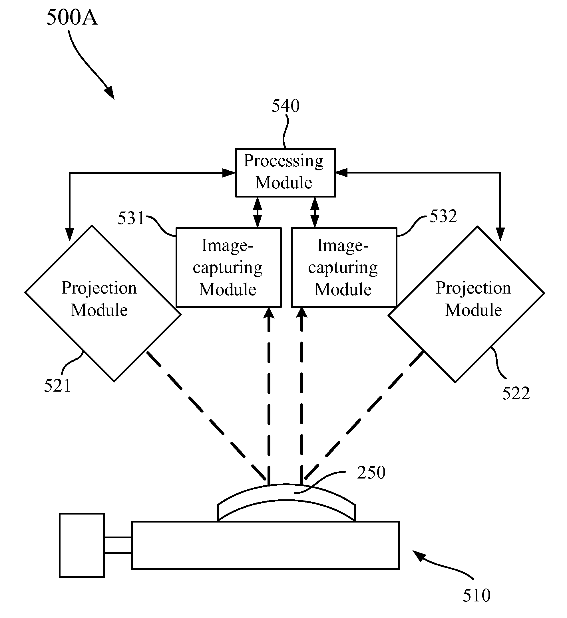
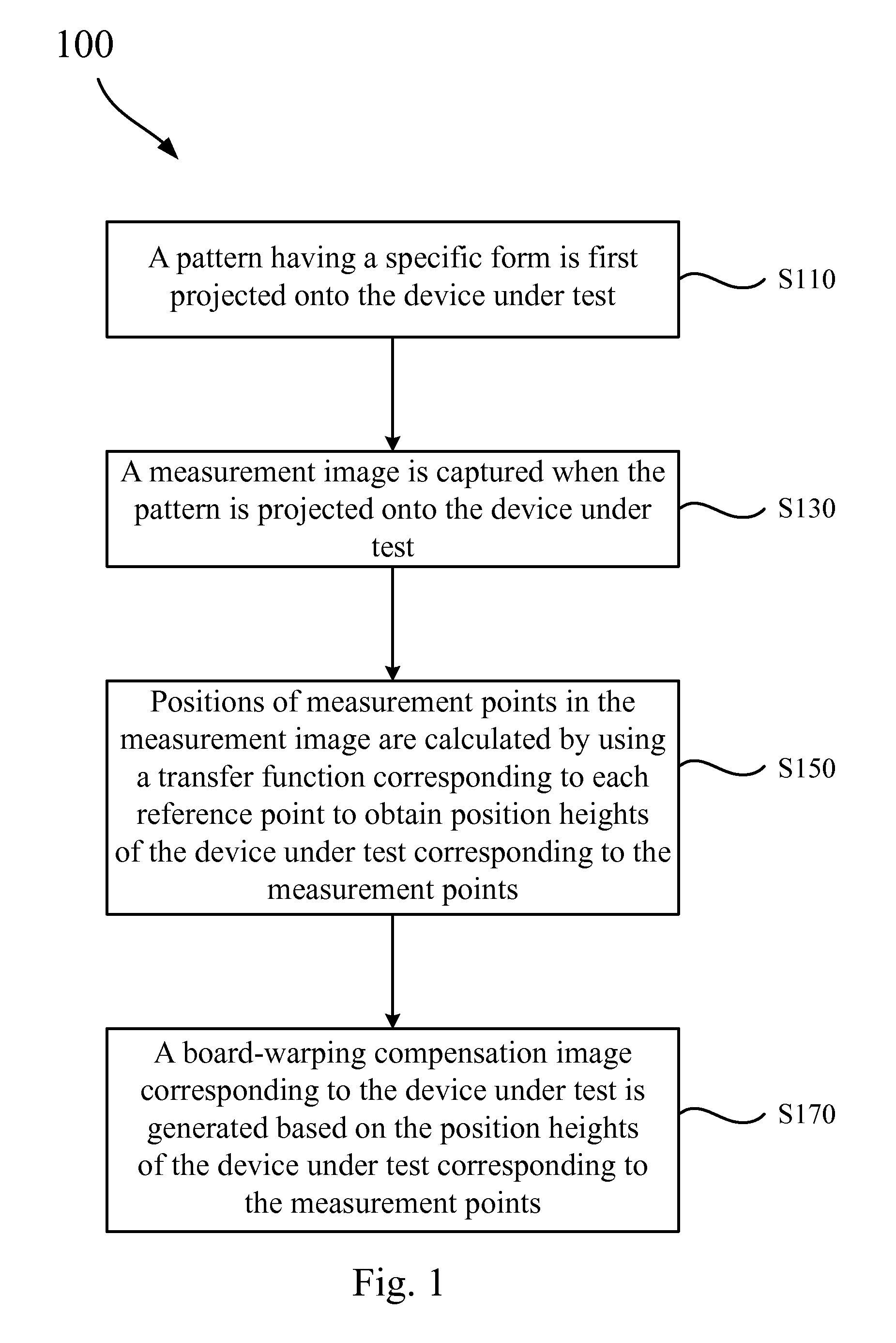
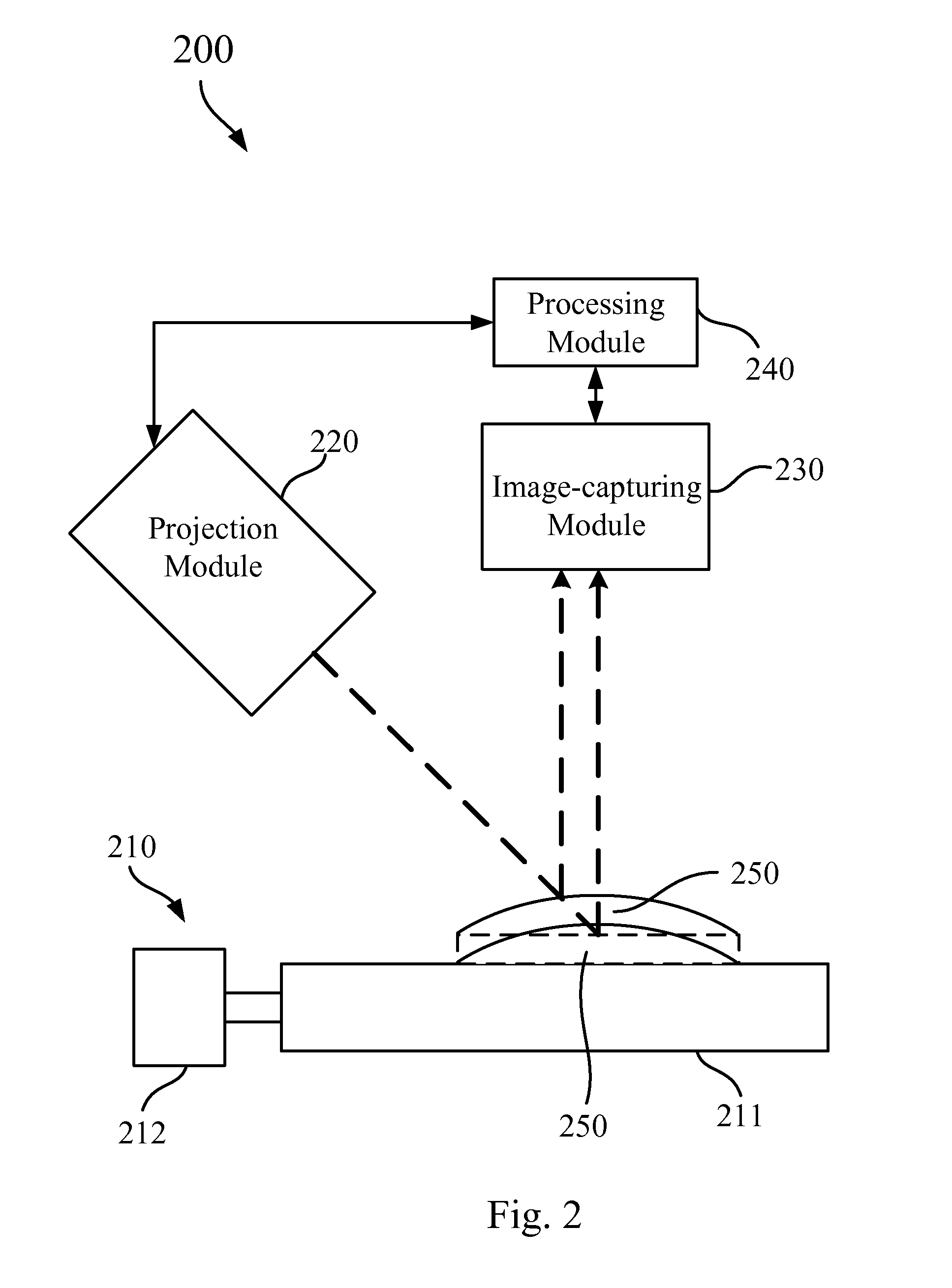
The present invention provides a method and apparatus for measuring the warping of a device's board. This method involves capturing a measurement image of the device, selecting an area of the image where the device is located, and selecting N effective measurement points from the image. These points are spaced apart and are selected based on the area under test. The method also involves generating a compensation image for the inclined or curved surface of the device to compensate for any deformation that may occur. The compensation image is based on the position heights of the device and the reference points in a pattern projected onto the device. By measuring the deformation and performing calibrations and compensation accurately, the method improves efficiency and accuracy in measuring board warping of the device.

Problems solved by technology

In practical applications, printed circuit boards may be impacted by external stress or gravity to cause board warping.
Board warping will result in a reduced accuracy when the device under test is measured by the measuring apparatus.
For example, because of the deviation of the device under test in the vertical direction caused by warpage of the board, portions of the device under test which are intended to be measured are not within an optimal range of image-capturing focal length.
However, only the height of a small part of the device under test can be calculated by utilizing the laser light.
Such a process will lead to poor measurement efficiency, resulting in too much time being spent on the process.

Method used


Image

  • Board-warping measuring apparatus and board-warping measuring method thereof
  • Board-warping measuring apparatus and board-warping measuring method thereof
  • Board-warping measuring apparatus and board-warping measuring method thereof

Examples


Embodiment Construction

[0045]Reference will now be made in detail to the present embodiments of the invention, examples of which are illustrated in the accompanying drawings. However, the embodiments provided herein are intended as illustrative only since numerous modifications and variations therein will be apparent to those skilled in the art. Description of the operation does not intend to limit the operation sequence. Any structures resulting from recombination of devices with equivalent effects are within the scope of the present invention. In addition, drawings are only for the purpose of illustration and not plotted according to the original size. Wherever possible, the same reference numbers are used in the drawings and the description to refer to the same or like parts.

[0046]As used herein, “around,”“about” or “approximately” shall generally mean within 20 percent, preferably within 10 percent, and more preferably within 5 percent of a given value or range. Numerical quantities given herein are a...


PUM


Abstract

A board-warping measuring method is configured to measure a device under test. The device under test is disposed on a measuring carrier. The board-warping measuring method includes: projecting a pattern onto the device under test, wherein the pattern includes plural reference points; capturing a measurement image by an image-capturing module when the pattern is projected onto the device under test, wherein the measurement image includes plural measurement points respectively corresponding to the reference points; calculating a position of each of the measurement points in the measurement image by utilizing a transfer function corresponding to each of the reference points to obtain position heights of the device under test corresponding to the measurement points; and compensating for board warping of the device under test based on the position heights of the device under test corresponding to the measurement points.

Description

RELATED APPLICATIONS[0001]This application claims priority to Taiwan Application Serial Number 104101799, filed Jan. 20, 2015, which is herein incorporated by reference.BACKGROUND[0002]1. Field of Invention[0003]The present invention relates to a board-warping measuring apparatus. More particularly, the present invention relates to a board-warping measuring apparatus having a projection module for projecting a pattern onto a device under test.[0004]2. Description of Related Art[0005]In recent years, due to the reduction in the size of devices, many different types of automatic high-precision testing equipment have been developed for detecting the appearance of electronic components, wire connections, and whether alignment is correct. For example, automatic solder paste inspectors have been widely utilized in production lines to accurately measure the amount of solder pasted on substrates so as to serve as a necessary tool for process control in printed circuit board manufacturing.[0...

Claims


Application Information

Patent Timeline
IPC IPC(8): G01B11/16G01B11/25
CPCG01B11/167G01B11/2513G01B11/2504G01B11/306
Inventor YU, LIANG-PINPAN, YING-LINLIN, CHI-YANG
Owner TEST RES INC
Learn More