
Display device

a display device and display technology, applied in static indicating devices, non-linear optics, instruments, etc., can solve the problems of not being able to fulfill the desire of manufacturers, difficult to make the display section and the frame area a uniform color, and not appearing to be uniform, so as to reduce the number of polarizing plates, reduce the level difference and the optical properties. , the effect of reducing the number of parts

Active Publication Date: 2016-07-21
ALPINE ELECTRONICS INC
View PDF3 Cites 9 Cited by
  • Summary
  • Abstract
  • Description
  • Claims
  • Application Information

AI Technical Summary

Benefits of technology

The liquid crystal shutter described in this patent has several technical benefits. First, the design has the same appearance across the entire surface of the shutter, which makes it easier to manufacture. Second, the design allows for different voltage frequencies and potentials to be applied to different areas of the shutter, without the need for separate arrangements. Third, overcoat layers are used to reduce differences in optical properties between the electrodes and their surroundings. Fourth, the design can be used in a liquid crystal display device with a backlight, where the transparency of the display can be adjusted by varying the voltage applied to the electrodes. Fifth, the design allows for the total dimming ratio in a combination of the liquid crystal display device and the liquid crystal shutter to be expanded by varying the transparency of the first area.

Problems solved by technology

There is a problem with the above-described display device disclosed in JP 2006-220786 A in that, due to a structural difference between the display section and its surrounding frame area, they do not appear to be a uniform color in a strict sense as seen from the surface side when the display section is not active (i.e. the device for displaying various kinds of information on the display section is not powered on).
However, until now, it has been physically difficult to make the display section and the frame area a uniform color, and the desire of manufacturers has not been able to be fulfilled.

Method used


Image

  • Display device
  • Display device
  • Display device

Examples


first embodiment

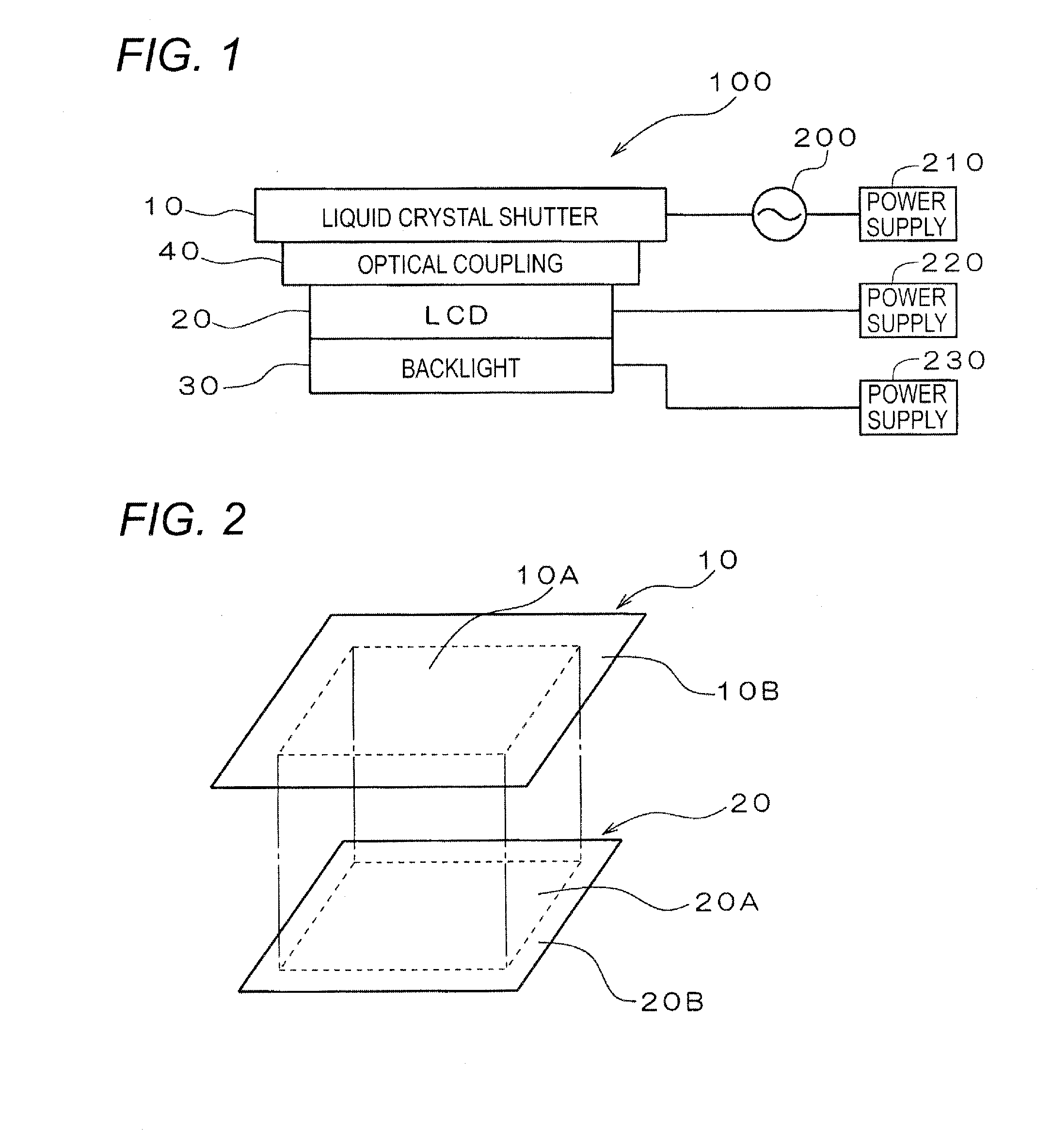
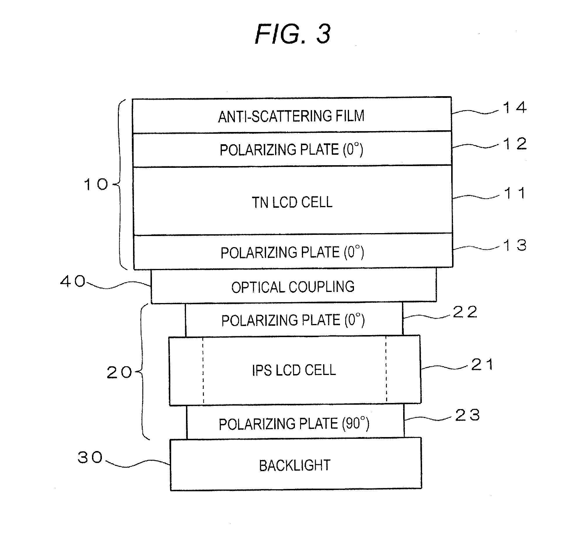
[0053]FIG. 1 illustrates the configuration of a display device according to a first embodiment. As shown in FIG. 1, the display device 100 according to this embodiment includes a liquid crystal shutter 10, liquid crystal display device (LCD) 20, backlight 30, and an optical coupling 40.

[0054]The liquid crystal shutter 10 is layered on the liquid crystal display device 20 as a displaying unit having a display area and its surrounding hidden area, and has a first area corresponding to the display area and a second area corresponding to the hidden area. The optical coupling 40 is used between the liquid crystal shutter 10 and the liquid crystal display device 20 to join them with no optical gap. Further, under the liquid crystal display device 20 (i.e. on the side opposite the liquid crystal shutter 10), the backlight 30 is located. A power supply 220 and a power supply 230 are connected to the liquid crystal display device 20 and the backlight 30, respectively, to apply the voltage re...

second embodiment

[0100]Although in the above-described embodiment the entire display area 20A of the liquid crystal display device 20 has been described as starting its display operation as a unit and then terminating the display operation, the present invention can still be applied to a case where a display area 20A is divided into a plurality of division areas and display operation is started / terminated for each division area, by combining a liquid crystal shutter 10 with a liquid crystal display device 20.

[0101]FIG. 8 illustrates the positional relationship between a liquid crystal shutter 10′ and a liquid crystal display device 20 according to a second embodiment. As shown in FIG. 8, the liquid crystal display device 20 includes a display area 20A and a hidden area 20B. The display area 20A is an area capable of displaying various kinds of information using the liquid crystal display device 20. It is assumed that in this embodiment the liquid crystal display device 20 is capable of switching bet...


PUM

PropertyMeasurementUnit
angleaaaaaaaaaa
angleaaaaaaaaaa
areaaaaaaaaaaa

Abstract

A display device includes a liquid crystal display device that has a display area and a hidden area surrounding the display area; a liquid crystal shutter that is layered on the liquid crystal display device and has a first area corresponding to the display area and a second area corresponding to the hidden area; and a control unit that sets the first and second areas to a transparent state and an opaque state, respectively, when the display area is active, and sets the first and second areas to the opaque state when the display area is not active.

Description

RELATED APPLICATION[0001]The present application claims priority to Japanese Patent Application Numbers 2015-007299, filed Jan. 17, 2015, and 2015-164073, filed Aug. 21, 2015, the entirety of which are hereby incorporated by reference.BACKGROUND[0002]1. Field of the Invention[0003]The present invention relates to a display device for displaying various kinds of information.[0004]2. Description of the Related Art[0005]Conventionally, a display device having a frame area around its display section is known (see, for example, JP 2006-220786 A). In the frame area of this display device, a light-shielding resin layer is provided on the backside of a surface glass substrate, thereby hiding various circuits provided under the light-shielding resin layer, such as a driver, from being exposed to the surface.[0006]There is a problem with the above-described display device disclosed in JP 2006-220786 A in that, due to a structural difference between the display section and its surrounding fram...

Claims


Application Information

Patent Timeline
Patent Type & Authority Applications(United States)
IPC IPC(8): G02F1/137G02F1/1333G02F1/1335G02F1/1337G02F1/1343
CPCG02F1/137G02F1/1337G02F2001/133567G02F1/133528G02F1/13338G02F1/13439G02F1/133512G02F1/1347G02F2203/62G02F1/13332G02F1/133567
Inventor YASUMOTO, TAKASHI
Owner ALPINE ELECTRONICS INC
Learn More