Eureka AIR delivers breakthrough ideas for toughest innovation challenges, trusted by R&D personnel around the world.

Method making it possible to produce the ideal curvature of a rod of vertebral osteosynthesis material designed to support a patient's vertebral column

a technology of vertebral osteosynthesis and ideal curvature, which is applied in the direction of internal osteosynthesis, osteosynthesis devices, instruments, etc., can solve the problems of extending the operation time, unable to exclude the risk of implanting a rod with an ideal curvature, and difficulty in achieving the ideal curvature of a straight rod for a surgeon

Active Publication Date: 2016-07-21
MEDICREA INT SA
View PDF0 Cites 25 Cited by
  • Summary
  • Abstract
  • Description
  • Claims
  • Application Information

AI Technical Summary

Benefits of technology

The invention is a method for treating a vertebral column by using a rod to correct spinal deformities. The method involves taking a sagittal preoperative X-ray of the spine, identifying the sacral slope, the pelvic parameters, and the position of the apical vertebral body. A wire modeling of the spine is then performed using CAD software. The method allows for the accurate measurement of the distance between the vertebral bodies and the position of the anchor members for anchoring the rod to the vertebral column. The position of the rod is then determined and the correction is made accordingly. The method helps to accurately correct spinal deformities and achieve a desired postoperative apex point.

Problems solved by technology

It has been shown that imparting the appropriate curvature to a straight rod may be very difficult for a surgeon, the curvature being more or less pronounced in any given location of the rod.
The trial and error necessary to obtain an appropriate curvature have the significant drawback of extending the operation time, which is not desirable for the patient, and the risk of implanting a rod with a non-ideal curvature cannot be ruled out.

Method used


Image

  • Method making it possible to produce the ideal curvature of a rod of vertebral osteosynthesis material designed to support a patient's vertebral column
  • Method making it possible to produce the ideal curvature of a rod of vertebral osteosynthesis material designed to support a patient's vertebral column
  • Method making it possible to produce the ideal curvature of a rod of vertebral osteosynthesis material designed to support a patient's vertebral column

Examples


Embodiment Construction

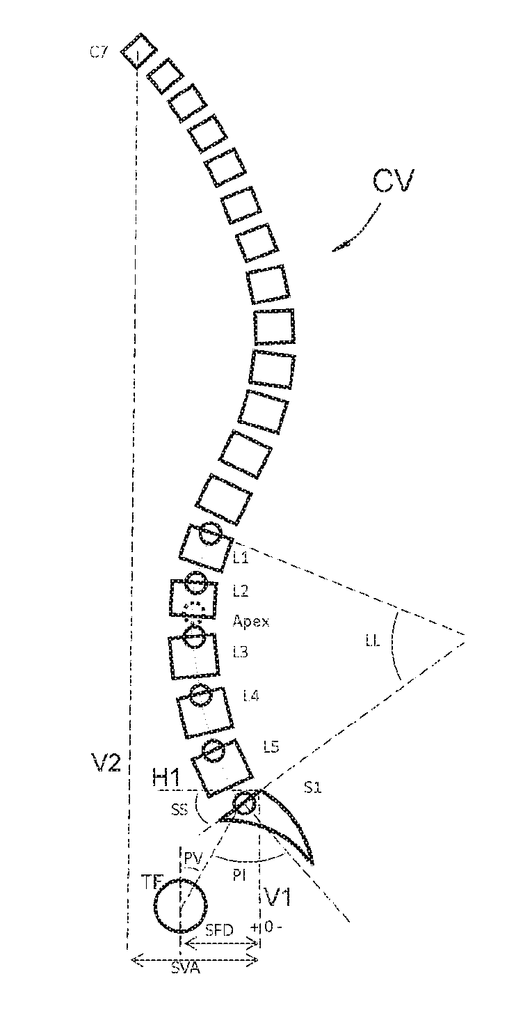
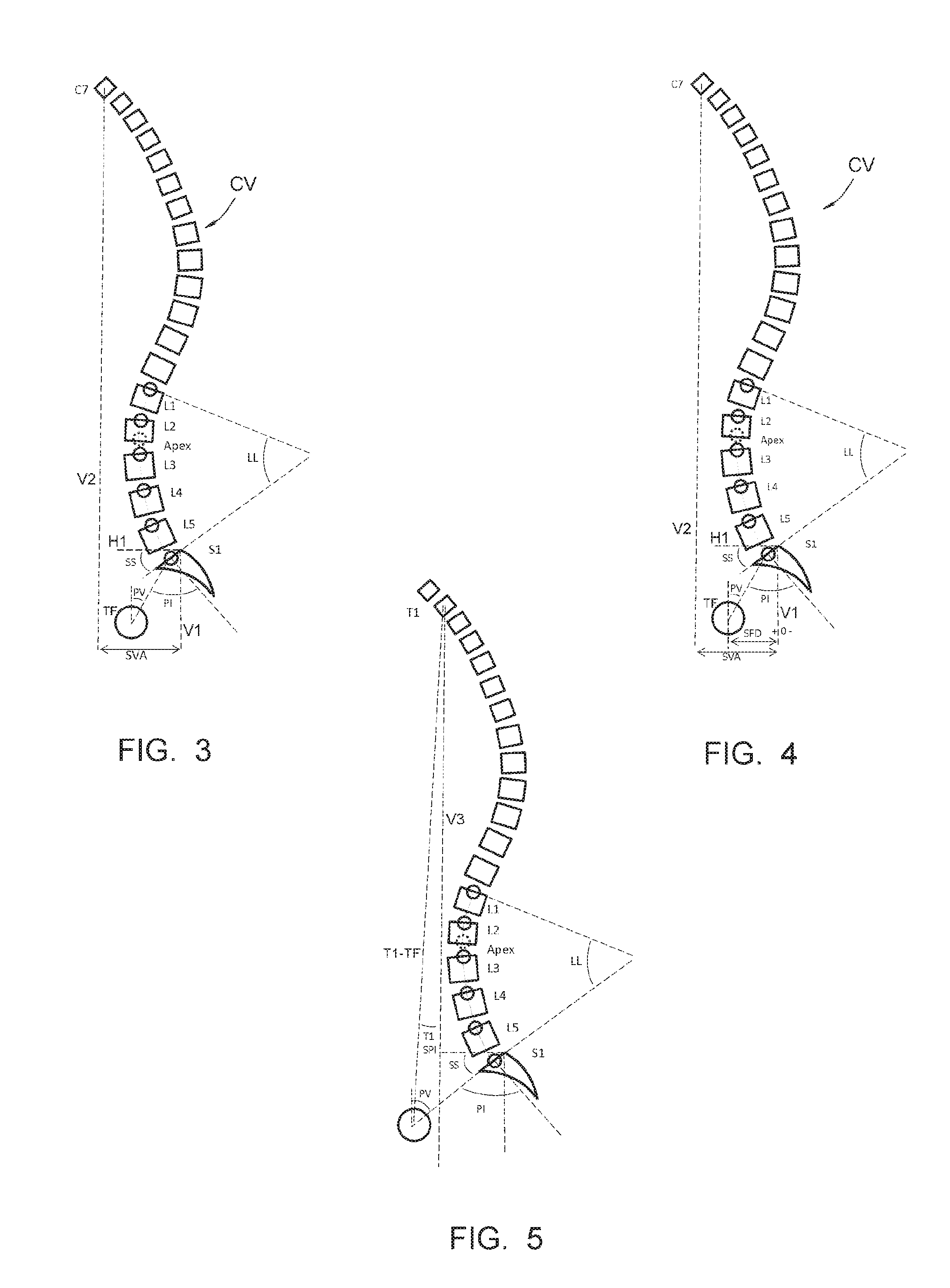
[0060]FIG. 3 very diagrammatically shows a vertebral column CV, and includes the following information:

[0061]LL: vertebral segment to be treated;

[0062]L1, L2, L3, L4, L5, S1, C7: the first, second, third, fourth and fifth lumbar vertebrae, the first vertebra of the sacrum and the seventh cervical vertebra, respectively;

[0063]Apex: the forward most point of the vertebral column;

[0064]SS, PV, PI: the aforementioned pelvic criteria;

[0065]TF: the femoral heads, shown by a circle;

[0066]H1 and V1: the horizontal and vertical, respectively, at the posterior upper point of the plate of S1;

[0067]V2: the vertical passing through the center of the 7th cervical vertebra (C7).

[0068]FIG. 4 also mentions a so-called “SFD” value, going from the vertical V1 to the vertical passing through the center of the femoral heads TF.

[0069]FIG. 5 also mentions a so-called “T1 / SPI” value, which is the angle formed between the T1-TF segment going from the center of the first dorsal vertebra, called T1, to the ce...


PUM


Abstract

The method according the the invention comprises the following steps: a) taking a sagittal preoperative x-ray of the vertebral column of the patient to be treated, extending from the cervical vertebrae to the femoral heads; b) on that x-ray, identifying the pelvic parameters, the lumbar lordosis, the position of the apical lumbar vertebra, distances called SVA and SFD and a cloud of points; c) deducing, among predetermined morphotypes, the morphotype to which the treated vertebral column corresponds and deducing therefrom the desired postoperative apex point; d) positioning the different points of the cloud of points in a reference centered at the plate of S1; e) simulating the correction to be applied to the lumbar segment to be treated, by defining co-radial arcs situated below and above the desired postoperative apex point; defining two arcs concentric to the two curvatures obtained, which are tangent to each other at the apex point; f) translating these arcs away from the mean line of the vertebral column and defining a two- or three-dimensional model of the rod to be implanted, curved along the arcs.

Description

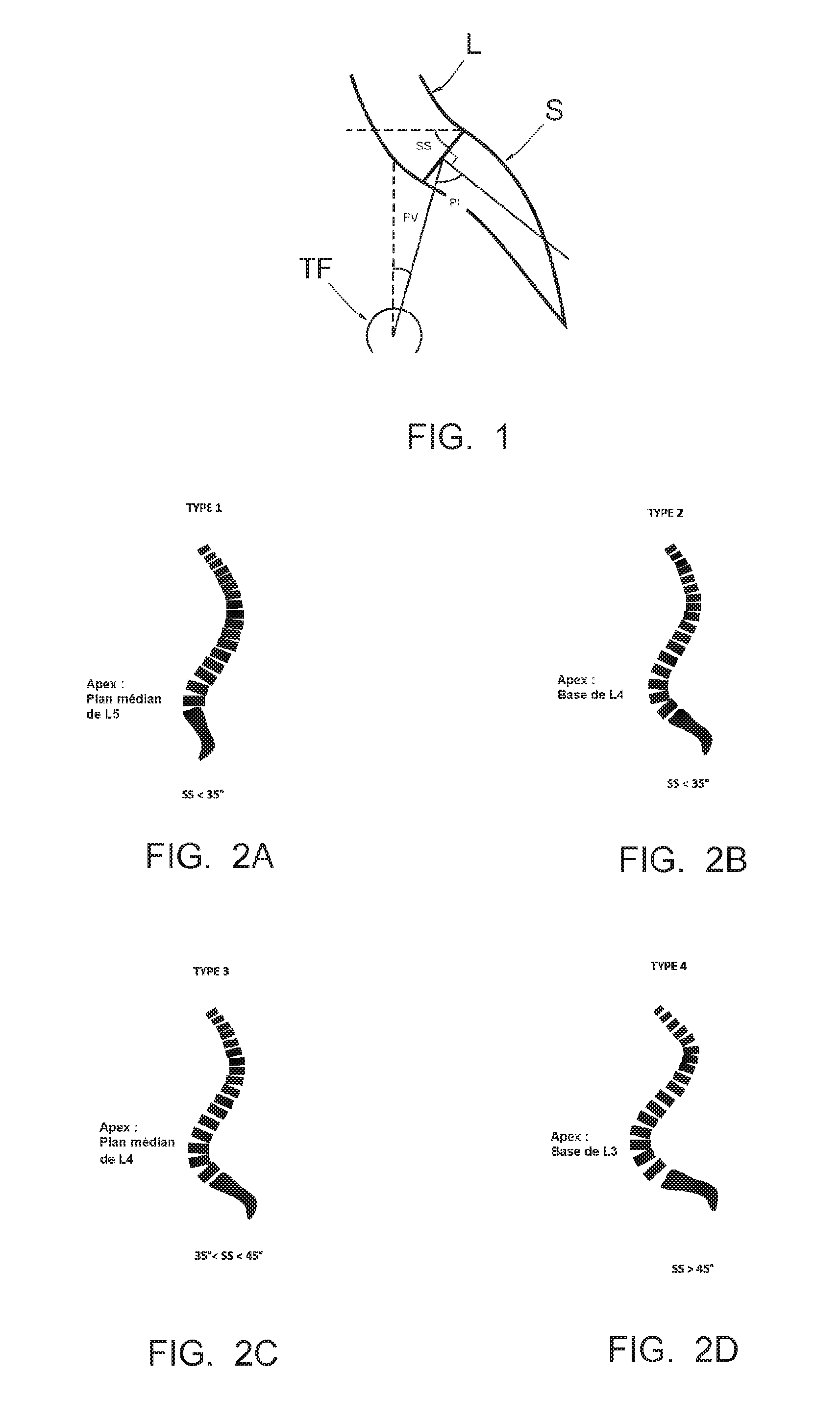
CROSS REFERENCE TO RELATED APPLICATION[0001]This application is a national stage entry of PCT / IB2014 / 064586 filed Sep. 17, 2014, under the International Convention claiming priority over French Patent Application No. 1358988 filed Sep. 18, 2013.FIELD OF THE INVENTION[0002]The present invention relates to a method making it possible to produce the ideal curvature of a rod of vertebral osteosynthesis material designed to support a patient's vertebral column.BACKGROUND OF THE INVENTION[0003]It is known to analyze a patient's vertebral column in reference to so-called “pelvic” parameters and different morphotypes of a vertebral column, documented in the scientific literature. The appended FIG. 1 very diagrammatically shows the base of the vertebral column, i.e., part of the lumbar vertebrae L and the sacrum S, as well as the femoral heads TF; the aforementioned pelvic criteria are:[0004]the SS (sacral slope) criterion, which is the incline angle of the plate of S1 (first vertebra of the...

Claims


Application Information

Patent Timeline
IPC IPC(8): G06F17/50
CPCG06F17/50A61B17/7011A61B2017/568A61B34/10A61B2034/105A61B2034/108G06F30/00
Inventor MOSNIER, THOMASRYAN, DAVIDFIERE, VINCENT
Owner MEDICREA INT SA
Why Eureka
Eureka Blog
Learn More