Electric power tool

Active Publication Date: 2016-07-21
MAKITA CORP
View PDF12 Cites 2 Cited by
  • Summary
  • Abstract
  • Description
  • Claims
  • Application Information

AI Technical Summary

Benefits of technology

The invention is about a way to cool a brush in an electric power tool. The brush has a close contact with a commutator motor, which generates heat. The metal sleeve that holds the brush gets high temperature. The rotating shaft of the rotator has a fan for cooling the motor. However, the metal sleeve is not effectively cooled at the mounting surface. To solve this problem, the invention proposes a new brush holder design. The design has a partition plate or a cutout part to enhance cooling of the metal sleeve. The brush holder also has a flange portion, turbulence rib, or unevenness at the bottom face of the metal sleeve to further enhance heat radiation. A ventilation passage is also designed to enhance cooling of the metal sleeve by allowing air to flow directly through the passage. Overall, the invention improves the cooling efficiency of the brush in the electric power tool.

Problems solved by technology

The brush has slide contact with the commutator by the driving of the commutator motor, which results in generation of heat.
Then, the metal sleeve gets high temperature.
However, since the metal sleeve is mounted on the resin base in close contact, the metal sleeve is not cooled effectively at the mounting surface, and the resin base possibly melts when the metal sleeve gets high temperature.
However, when the brush holder is held in a direction that the metal sleeve is disposed at the opposite side of the fan across the resin base, flow of the cooling air is interfered with the resin base.

Method used


Image

  • Electric power tool
  • Electric power tool
  • Electric power tool

Examples


Embodiment Construction

[0025]The following describes embodiments of the present invention with referring to the drawings.

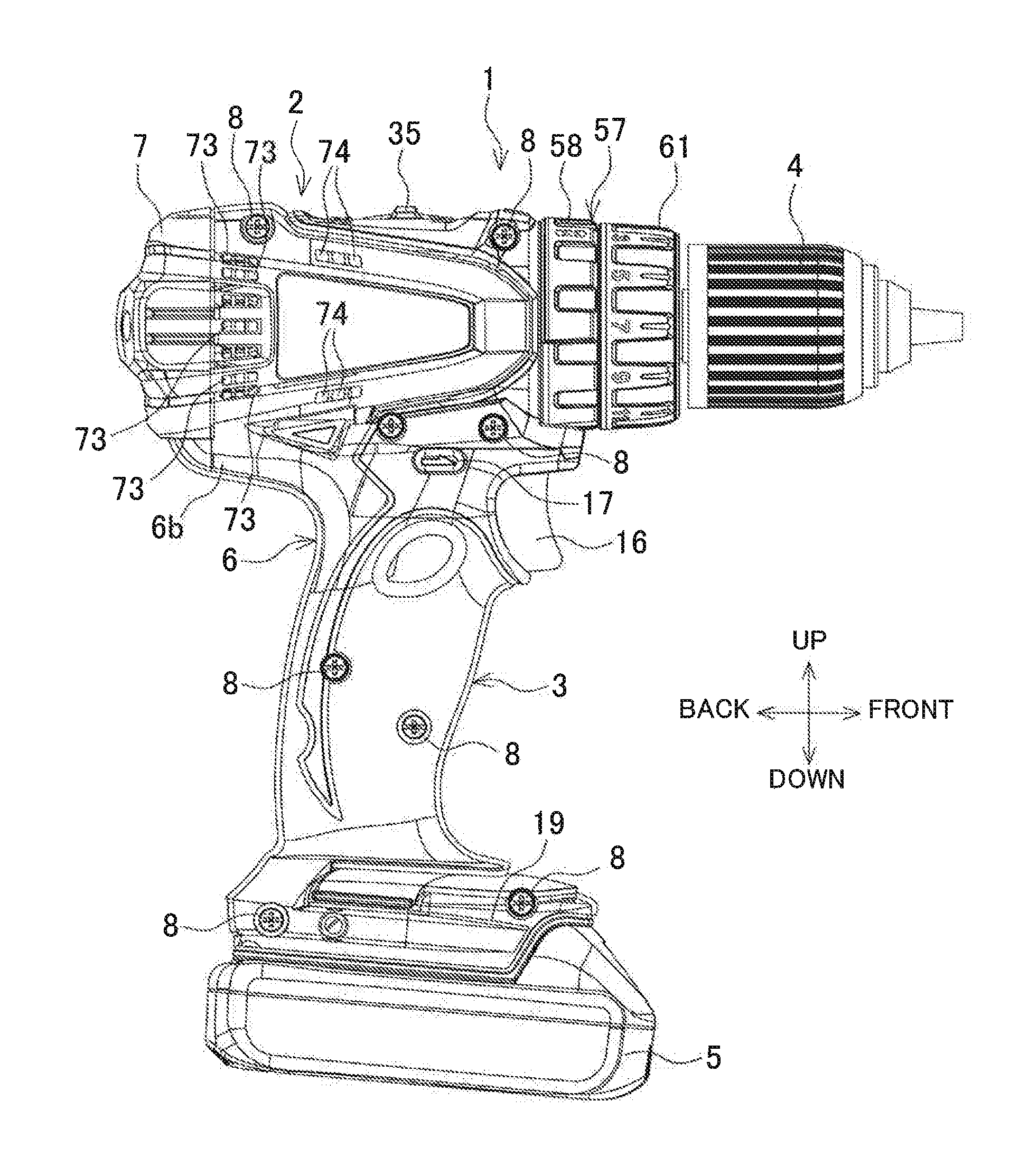
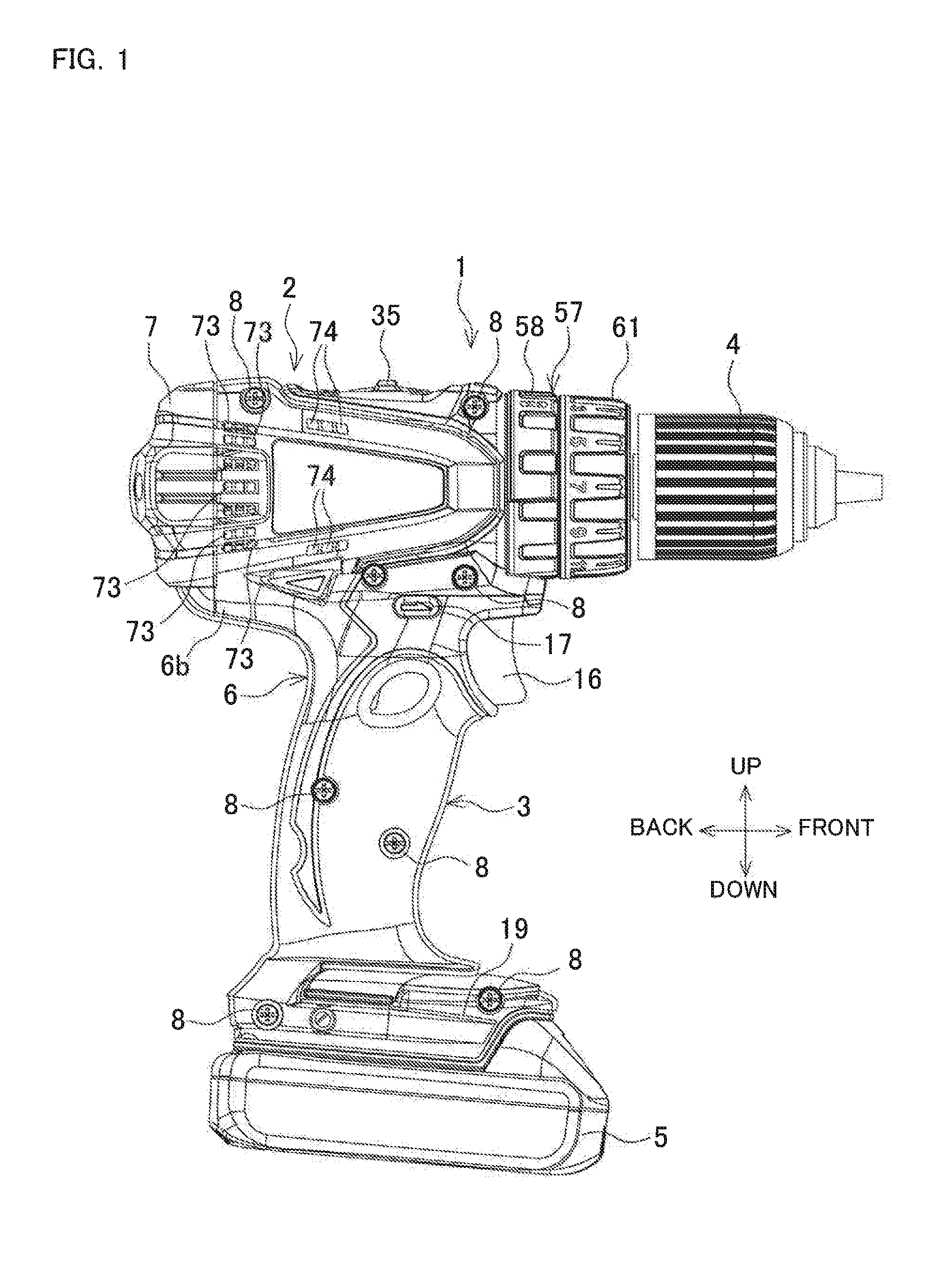
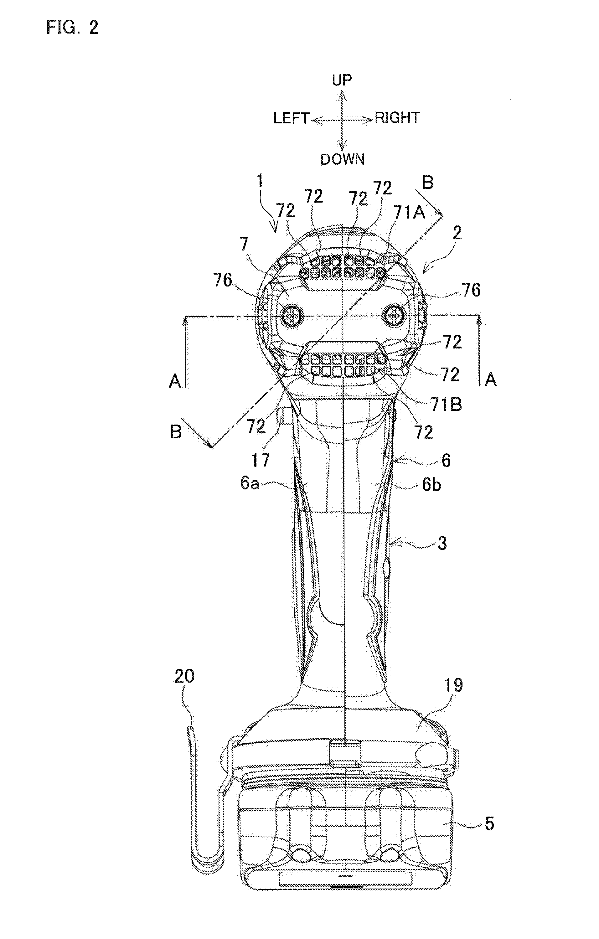
[0026]FIG. 1 is a side view of a vibration driver drill indicating an exemplary electric power tool. FIG. 2 is a back view. FIG. 3 is a back view in a state where a rear cover is removed. FIG. 4 is a partial vertical cross-sectional view. A vibration driver drill 1 is T-shaped from the side view with a handle 3 projecting from a lower side of a main body 2 extending in the front-rear direction. At a front end of the main body 2, a drill chuck 4, which can grip a bit at the tip, is disposed. At a lower end of the handle 3, a battery pack 5 as a power source is mounted. The housing of the embodiment is constituted of a cap shaped rear cover 7 attached to a rear part of a main body housing 6 where the rear half portion of the main body 2 and the handle 3 are jointly provided. The main body housing 6 is formed of a left half housing 6a and a right half housing 6b attaching by a plurality of...


PUM


Abstract

An electric power tool includes a housing, a commutator motor housed in the housing, and a brush holder disposed in the housing. A fan is disposed to the commutator motor. The brush holder includes a metal sleeve and a resin base. The metal sleeve houses a brush, and the resin base holds the metal sleeve at one surface side of the resin base. The resin base includes an opening portion exposing the metal sleeve to the opposite side surface of the one surface side. The brush holder is disposed in a direction that the resin base is disposed at the fan side such that rotation of the fan causes air suctioned from an air intake opening disposed in the housing at the metal sleeve side to be discharged from an exhaust outlet disposed in the housing at the fan side after passing through the brush holder and a commutator.

Description

BACKGROUND[0001]This application claims the benefit of Japanese Patent Application Number 2015-009690 filed on Jan. 21, 2015, the entirety of which is incorporated by reference.[0002]1. Technical Field[0003]The present invention relates to an electric power tool such as a vibration driver drill that uses a commutator motor as a driving source.[0004]2. Related Art[0005]In electric power tools such as a vibration driver drill and an impact driver, the electric power tool that uses a commutator motor as a driving source has been known. In this case, a structure, in which a brush holder is held orthogonally to a rotating shaft in a housing and a brush is brought into pressure contact with a commutator that passes through the brush holder, is employed. The brush holder is constituted of a cylindrical metal sleeve, which holds the brush, mounted on a disc-shaped resin base in the radial direction.[0006]The brush has slide contact with the commutator by the driving of the commutator motor,...

Claims


Application Information

Patent Timeline
IPC IPC(8): H02K13/00H02K7/14H02K9/06
CPCH02K13/00H02K7/145H02K9/06B25F5/001B25F5/008H02K9/28
Inventor NIWA, AKIRA
Owner MAKITA CORP
Why Eureka
Try Eureka