Oscillation circuit
a technology of oscillating circuits and oscillating components, applied in oscillating generators, pulse techniques, pulse generators, etc., can solve problems such as difficulty in preventing functional circuits from causing operational problems
- Summary
- Abstract
- Description
- Claims
- Application Information
AI Technical Summary
Benefits of technology
Problems solved by technology
Method used
Image
Examples
first embodiment
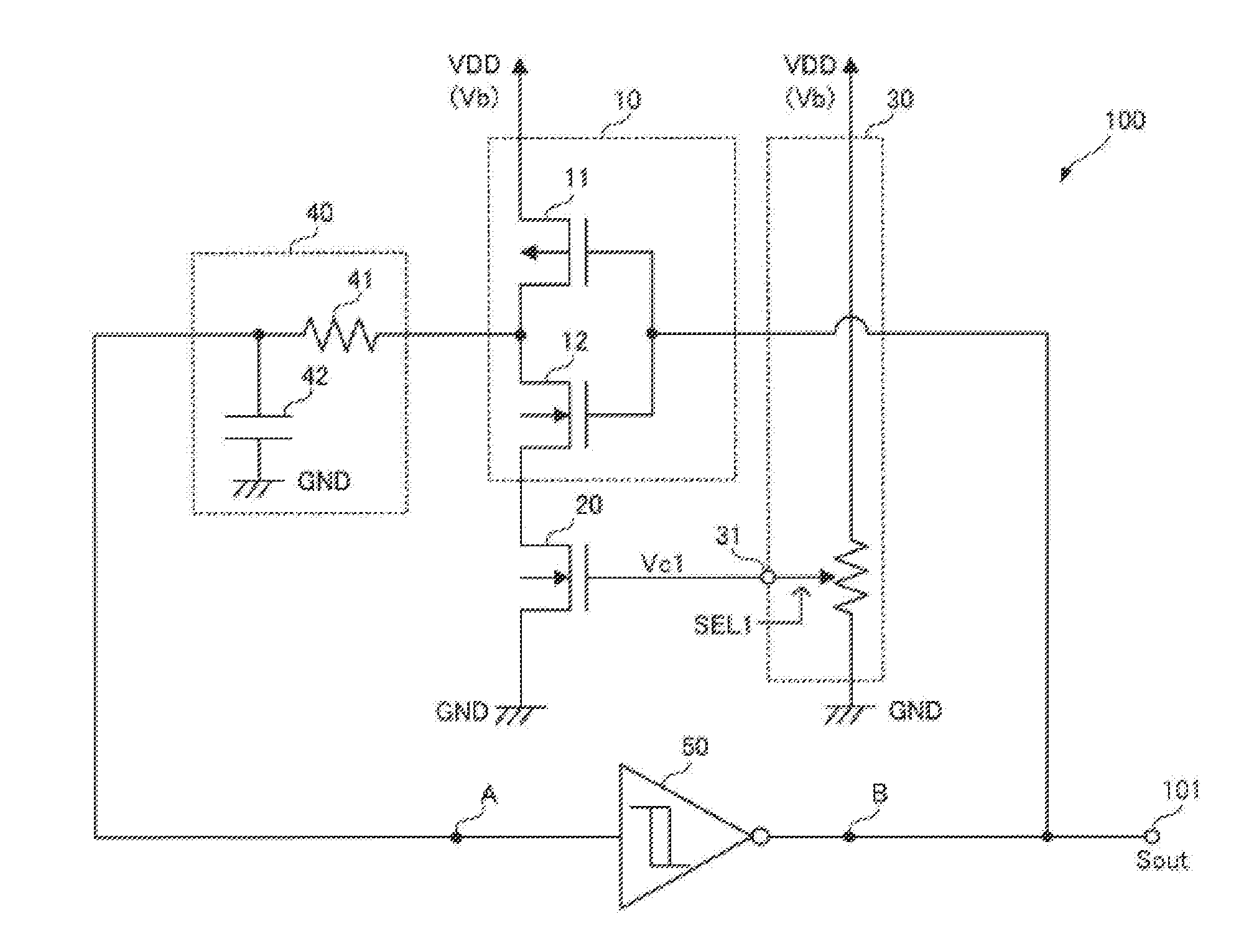
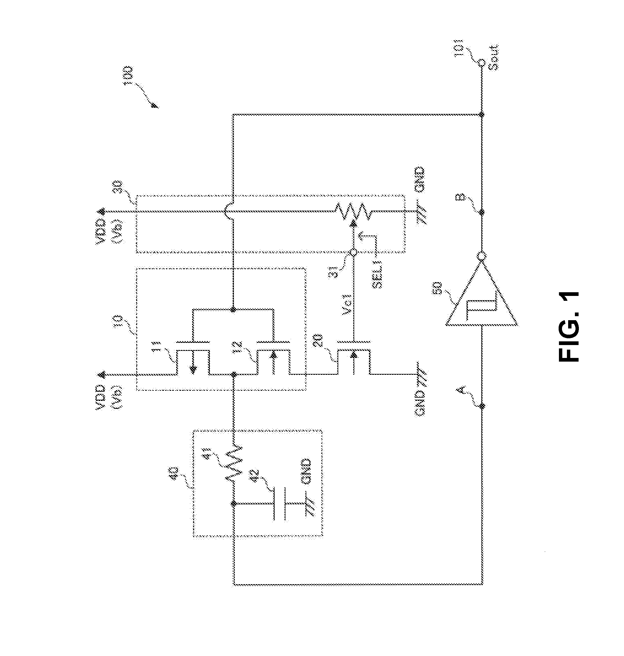
[0027]A first embodiment of the present invention will be explained. FIG. 1 is a circuit diagram showing a configuration of an oscillation circuit 100 according to the first embodiment of the present invention.
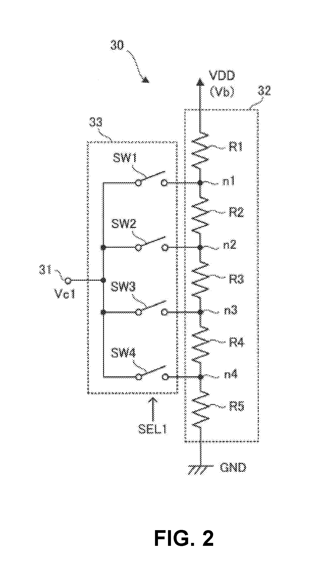
[0028]As shown in FIG. 1, the oscillation circuit 100 includes an inverter 10; an N-MOS transistor 20; a control voltage generating circuit 30; an RC circuit 40; and a Schmmit trigger circuit 50.
[0029]In the first embodiment, each component of the oscillation circuit 100 may be formed in one single semiconductor chip. It should be noted that the present invention is not limited to the structure, and each component of the oscillation circuit 100 may be formed in different semiconductor chips. Further, it should be noted that the RC circuit 40 may be formed of a discrete component.
[0030]In the first embodiment, the inverter 10 includes a P-MOS transistor 11 and an N-MOS transistor 12 connected in series. The P-MOS transistor 11 has a source connected to a power source line VDD; ...
second embodiment
[0066]A second embodiment of the present invention will be explained next. FIG. 6 is a circuit diagram showing a configuration of an oscillation circuit 100A according to the second embodiment of the present invention.
[0067]As shown in FIG. 6, the oscillation circuit 100A includes a control voltage generating circuit 30A having a configuration different from that of the control voltage generating circuit 30 of the oscillation circuit 100 in the first embodiment.
[0068]In the second embodiment, similar to the control voltage generating circuit 30 in the first embodiment, the control voltage generating circuit 30A is configured to generate the control voltage Vc1 having the magnitude corresponding to the power source voltage Vb supplied between the power source line VDD and the ground line GND. Further, the control voltage generating circuit 30A is configured to output and supply the control voltage Vc1 to the gate of the N-MOS transistor 20 through the output terminal 31.
[0069]More sp...
third embodiment
[0078]A third embodiment of the present invention will be explained next. FIG. 8 is a circuit diagram showing a configuration of an oscillation circuit 100B according to the third embodiment of the present invention.
[0079]As shown in FIG. 8, the oscillation circuit 100B includes a selection signal generating portion 60 in addition to the configuration of the oscillation circuit 100A in the second embodiment.
[0080]In the third embodiment, the selection signal generating portion 60 is configured to generate the selection signal SEL1 and the selection signal SEL2 for setting the voltage division ratio of the control voltage generating circuit 30A. The selection signal generating portion 60 may be formed of, for example, a micro computer and a memory, so that the selection signal generating portion 60 executes a selection signal generating program stored in the memory to generate the selection signal SEL1 and the selection signal SEL2. It should be noted that the selection signal genera...
PUM
 Abstract
Description
Claims
Application Information
 - R&D
- Intellectual Property
- Life Sciences
- Materials
- Tech Scout
- Unparalleled Data Quality
- Higher Quality Content
- 60% Fewer Hallucinations
Browse by: Latest US Patents, China's latest patents, Technical Efficacy Thesaurus, Application Domain, Technology Topic, Popular Technical Reports.
© 2025 PatSnap. All rights reserved.Legal|Privacy policy|Modern Slavery Act Transparency Statement|Sitemap|About US| Contact US: help@patsnap.com


