Receiving coupler for contactless data link

a data link and capacitance coupler technology, applied in the field of capacitance couplers for non-contact or contactless signals and data transmission, can solve the problems of critical and complex use adverse effects on signal reception, and increase the cost of flexible printed circuit boards, so as to improve coupling efficiency, improve coupling capacitance, and increase the signal level

Active Publication Date: 2016-07-21
SCHLEIFRING GMBH
View PDF3 Cites 9 Cited by
  • Summary
  • Abstract
  • Description
  • Claims
  • Application Information

AI Technical Summary

Benefits of technology

[0009]The embodiments are directed to provide a receiving coupler that offers an improved coupling capacitance and therefore an improved coupling efficiency and an increased signal level in a capacitive rotary joint, further allowing to increase the distance between the receiving coupler and the transmission line. Furthermore, the receiving coupler should have a simple mechanical and electrical design and may be easily manufactured at low costs.

Problems solved by technology

The adhesive tape and the holding structure both affect the electrical field around the conductor pair and have an adverse effect to signal reception.
Things get worse, if the receiving coupler is not perfectly aligned with the transmission line.
Therefore, the use of a flexible printed circuit board is critical and complex.
This may result in a small overlapping region of the upper layer and the lower layer.

Method used


Image

  • Receiving coupler for contactless data link
  • Receiving coupler for contactless data link
  • Receiving coupler for contactless data link

Examples


Embodiment Construction

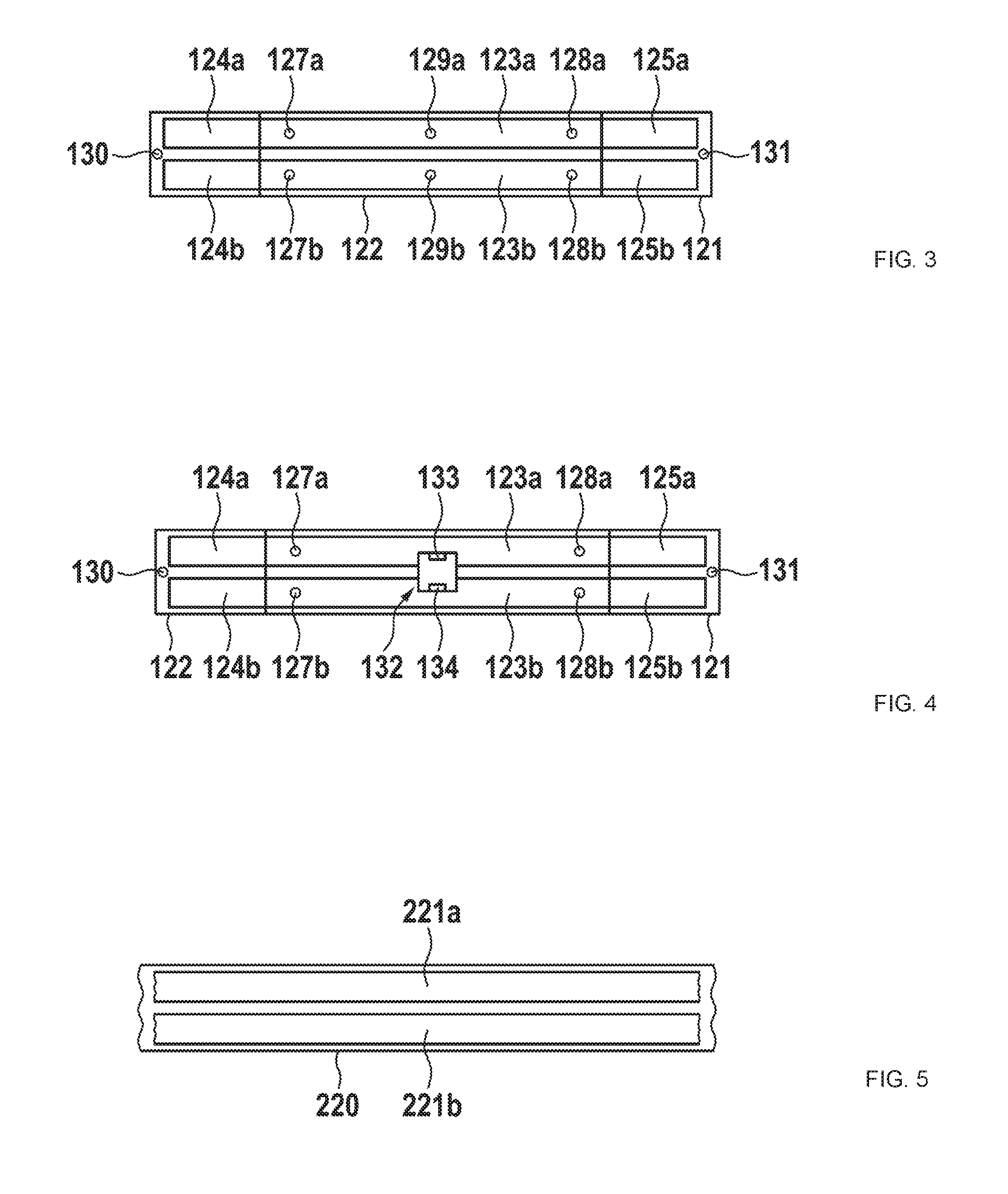
[0035]In the following embodiments, reference is made to an upper layer, lower layer, upper conductors and lower conductors. These relate to an orientation as shown in the Figures, specifically in FIG. 2. It is obvious that such a receiving coupler may be oriented in any orientation in three-dimensional space. The terms “upper” and “lower” are only used for simplification of explanation.

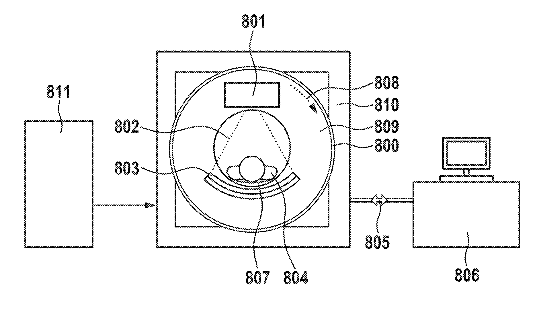
[0036]In FIG. 1, a first embodiment is shown. A contactless rotary joint which for example may be used in a computed tomography (CT) scanner may comprise a transmitting component 200 and a receiving component 100. The transmitting component 200 preferably is connected to the rotating part of a CT scanner gantry, whereas the receiving component 100 is connected to the stationary part for coupling data from the rotating to the stationary part of the CT scanner. The transmitting component 200 preferably comprises a transmitter support 210. This transmitter support may be a circular plastic carrier. It m...


PUM


Abstract

A receiving coupler for large diameter capacitive data links comprises at least two layers of isolating material, having different lengths and being attached to each other. The shorter layer comprises on its outer surface a first pair of conductors, whereas the longer layer comprises a second pair and a third pair of conductors. The conductors are connected to each other by vias. The stack of layers of different lengths can be adapted to various curve radii of transmitting components of a capacitive rotary joint.

Description

CROSS-REFERENCE TO RELATED APPLICATIONS[0001]This application claims priority from and benefit of the pending European Application No. 15151280.3 filed on Jan. 15, 2015. The above-mentioned European Application is incorporated herein by reference.BACKGROUND[0002]1. Field of the Invention[0003]The invention relates to capacitive couplers for non-contacting or contactless signal and data transmission, in particular to capacitive rotating transmission devices like rotary joints. Such transmission devices may be used in computer tomography scanners, also called CT scanners.[0004]2. Description of Relevant Art[0005]Capacitive rotating couplers, also called capacitive rotary joints are used to couple signals and data between parts rotating against each other. For example, in CT scanners, a rotating x-ray tube and an x-ray detector generate high-speed imaging data. The data may be transmitted from the rotating part to the stationary part. Furthermore, control signals for controlling the de...

Claims


Application Information

Patent Timeline
Patent Type & Authority Applications(United States)
IPC IPC(8): H03H7/00H03H3/00
CPCH03H3/00H03H7/004H01F38/14H01P1/06H01P1/062H04B5/0012H04B5/0031H01F2038/146A61B6/56H05K1/0239A61B6/032
Inventor WEITHMANN, HERBERTSTEFFENS, HOLGERTEKLOTH, MICHAEL
Owner SCHLEIFRING GMBH
Why Eureka
Try Eureka