
Testing and determining a threshold value

a threshold value and threshold value technology, applied in the field of critical stimulus level or critical symbol size testing, can solve the problems of test subject being forced to guess, test subject being more demanding to operate, test subject being stressed, etc., to achieve the effect of reducing space needed, convenient portability of the device, and easy light-weigh

Active Publication Date: 2016-08-04
OCUSPECTO
View PDF5 Cites 11 Cited by
  • Summary
  • Abstract
  • Description
  • Claims
  • Application Information

AI Technical Summary

Benefits of technology

The present invention provides an effective, easy, and reliable method for testing and determining a threshold value in psychometric tests in the field of ophthalmology, neuro-ophthalmology, and visual neuropsychology. This method can be used to test visual acuity, contrast sensitivity, color vision deficiency, and separation and sensitivity to disability glare. The invention combines different tests and devices together to create synergy, making the testing process more efficient. The display unit can be used with the perimeter surface and other testing devices, making the testing process more convenient.

Problems solved by technology

The problem with these methods is that in order to compensate for the differences between aggressively guessing test subject and cautious test subject, the test subject is forced to guess even when the symbol is not seen.
Increasing the amount of alternatives makes the test more demanding to operate for the test subject and stressful for the test subject.

Method used


Image

  • Testing and determining a threshold value
  • Testing and determining a threshold value
  • Testing and determining a threshold value

Examples


Embodiment Construction

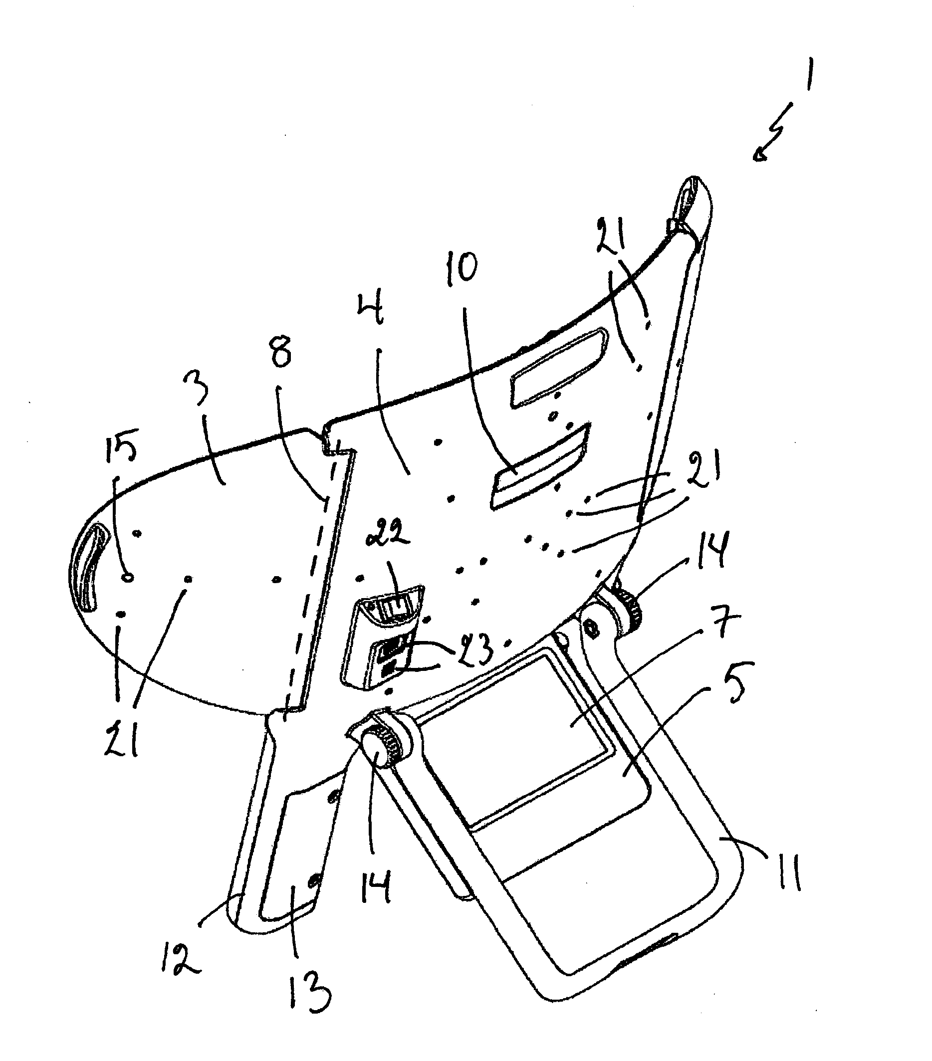
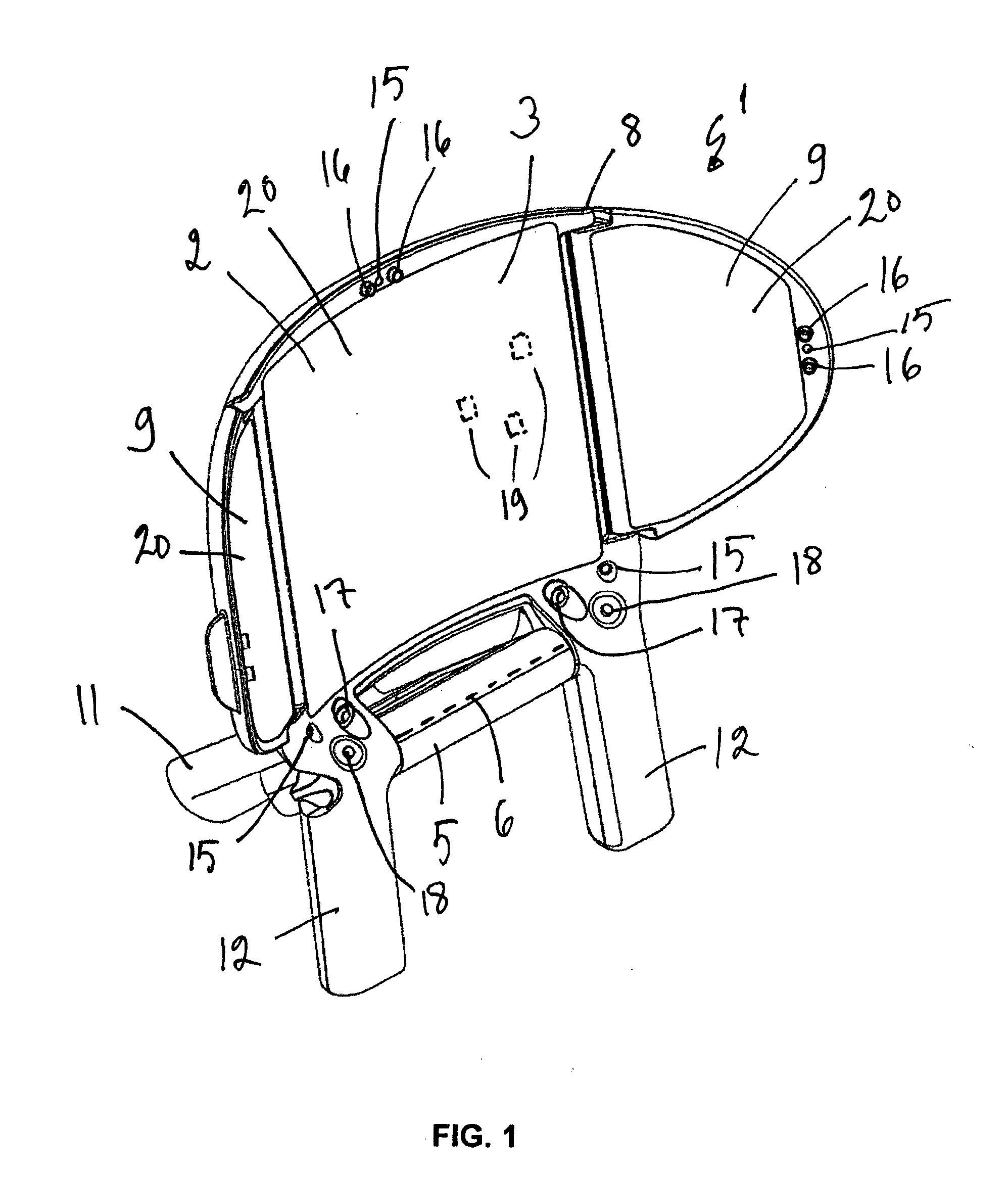
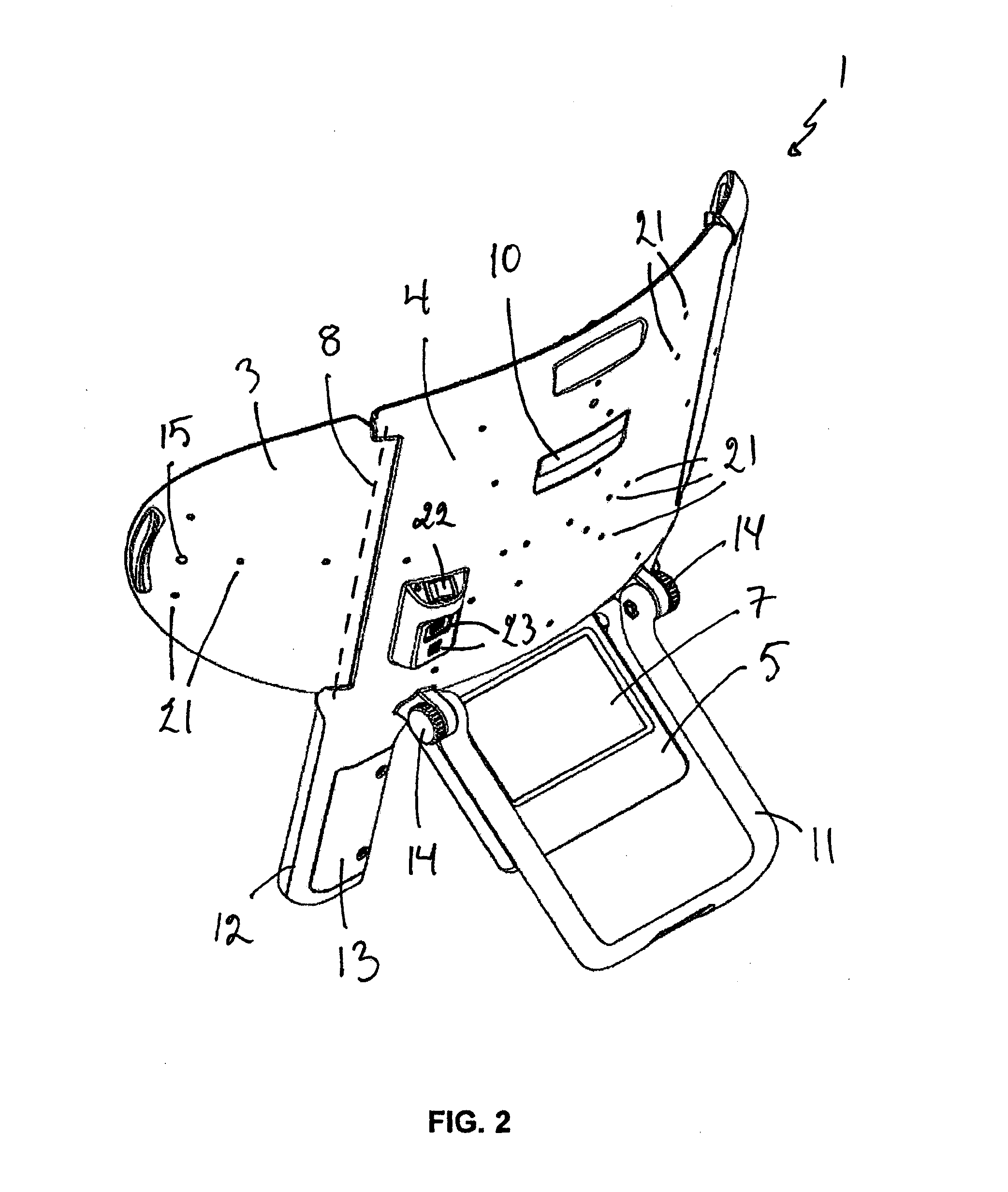
[0072]In this text the examples mainly speak of assessing whether a person fulfils driver requirements for safe driving, but the medical device and method according to the invention may be used in a variety of situations, e.g. diagnosing disease, job selection, visual competence assessment, school or community screenings, military selection, and disability classifications.

[0073]One method for testing a patient with a stand-alone medical device in one-piece configuration comprises at least the following steps:[0074]testing visual field of the patient with a first testing device comprising a perimeter device;[0075]testing one or more second tests with a second testing device, the second tests selected from the group of:[0076]a) testing of visual acuity,[0077]b) testing of contrast sensitivity,[0078]c) testing of glare;[0079]controlling the use of the first and second testing devices with a user interface device.

[0080]The medical device being stand-alone means that in a normal use situ...


PUM


Abstract

This invention relates to testing and determining a threshold value used in psychometric testing in field of ophthalmology, neuro-ophthalmology and visual neuropsychology. The method comprises at least the following steps:a) displaying a symbol with a distinctive visual appearance and with a stimulus level to a display at a stimulus time-point, the symbol selected from a group of possible symbols,b) monitoring if a response is given on a response device with multiple choices, each choice representing a possible visual appearance or location of the symbol, andb1) if a response is not given in a response time-limit from the stimulus time-point, increasing the stimulus level of the symbol by a predetermined step and returning to step a), orb2) if a response is given in the response time-limit from the stimulus time-point, comparing the response to symbol displayed in step a), andc1) if the response does not correspond to the symbol displayed in step a), producing, e.g. displaying, an error feedback and returning to step a), orc2) if the response corresponds to the symbol displayed in step a), determining if stop criteria for the test is satisfied, andd1) if stop criteria for the test is not satisfied, decreasing the stimulus level by a predetermined step and returning to step a), ord2) if stop criteria for the test is satisfied, ending the test.

Description

TECHNICAL FIELD OF THE INVENTION[0001]The invention relates to critical stimulus level or critical symbol size testing, i.e. a method for testing and determining a threshold value in psychometric testing in field of ophthalmology, neuro-ophthalmology and visual neuropsychology, for example in testing of visual acuity, contrast sensitivity, color vision deficiency or sensitivity to disability glare of a person.TECHNICAL BACKGROUND[0002]Testing of visual acuity, contrast sensitivity and sensitivity to disability glare have traditionally needed assistance from test personnel and manual interpretation of the test subject's answers and manual reporting. While automating the test procedure it is important that the tests are reliable, fast and that they won't require continuous assistance or manual reporting work from test personnel.[0003]Most common psychometric tests are different multiple-alternative forced-choice methods. In these a person has to identify a symbol of variable size, con...

Claims


Application Information

Patent Timeline
IPC IPC(8): A61B5/16A61B3/06A61B3/02A61B3/032A61B3/028
CPCA61B3/0091A61B3/022A61B3/024A61B5/16A61B3/032A61B3/066A61B3/028A61B5/7445A61B5/163G09B7/00A61B3/0033A61B3/063A61B3/18H04N5/58
Inventor MANTYSALO, TAPIOLEINONEN, MARKKUKAASALAINEN, HARRISAMPINEN, KATARIINAOJALA, MARIKA
Owner OCUSPECTO
Learn More