Toothed Belt Driving Device for Bicycle
a technology of driving device and toothed belt, which is applied in the direction of gearing, transportation and packaging, hoisting equipment, etc., can solve the problems of reducing the friction coefficient between the pulley groove portion and the belt tooth portion, and achieve the effect of reliably suppressing the occurrence of jumping
- Summary
- Abstract
- Description
- Claims
- Application Information
AI Technical Summary
Benefits of technology
Problems solved by technology
Method used
Image

Examples
first embodiment
[0036]Hereinafter, a first embodiment of the present invention will be described with reference to drawings.
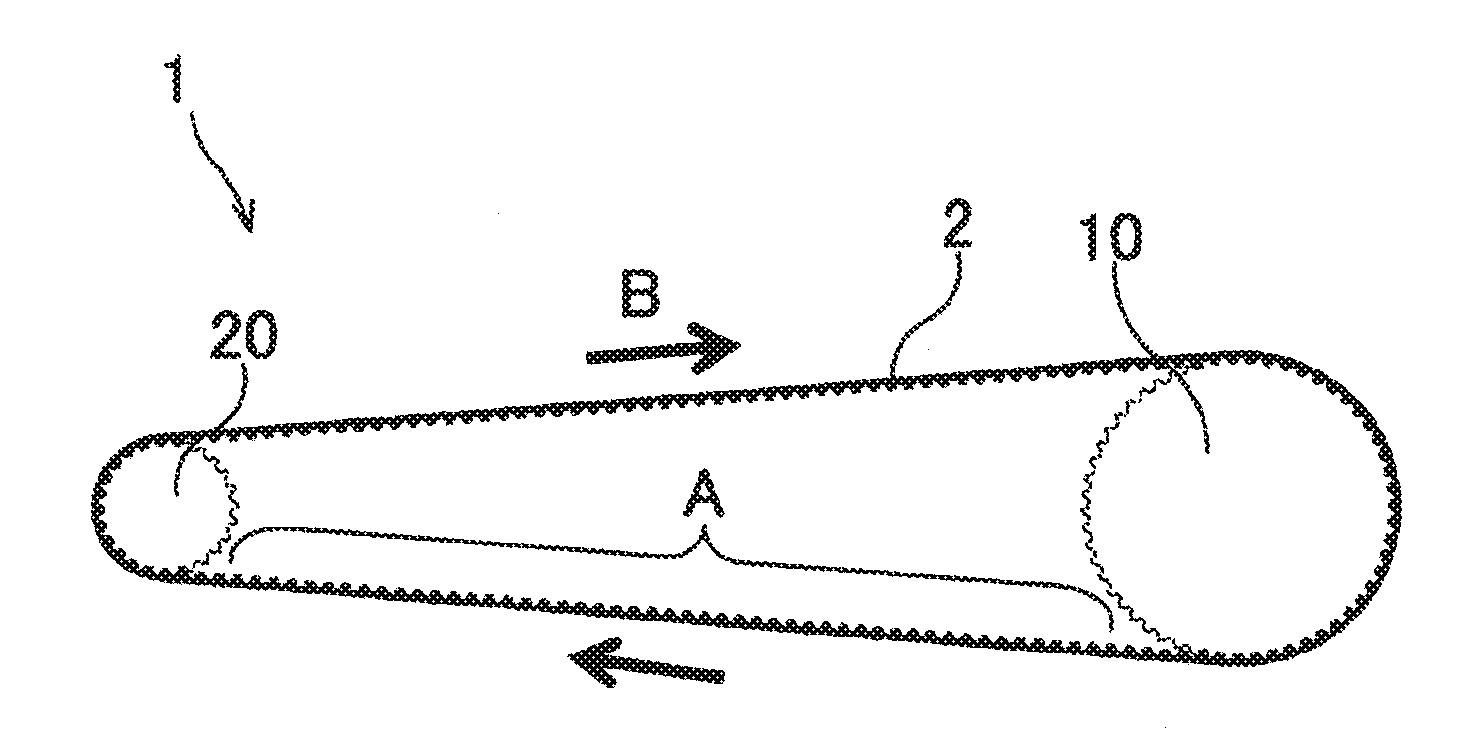
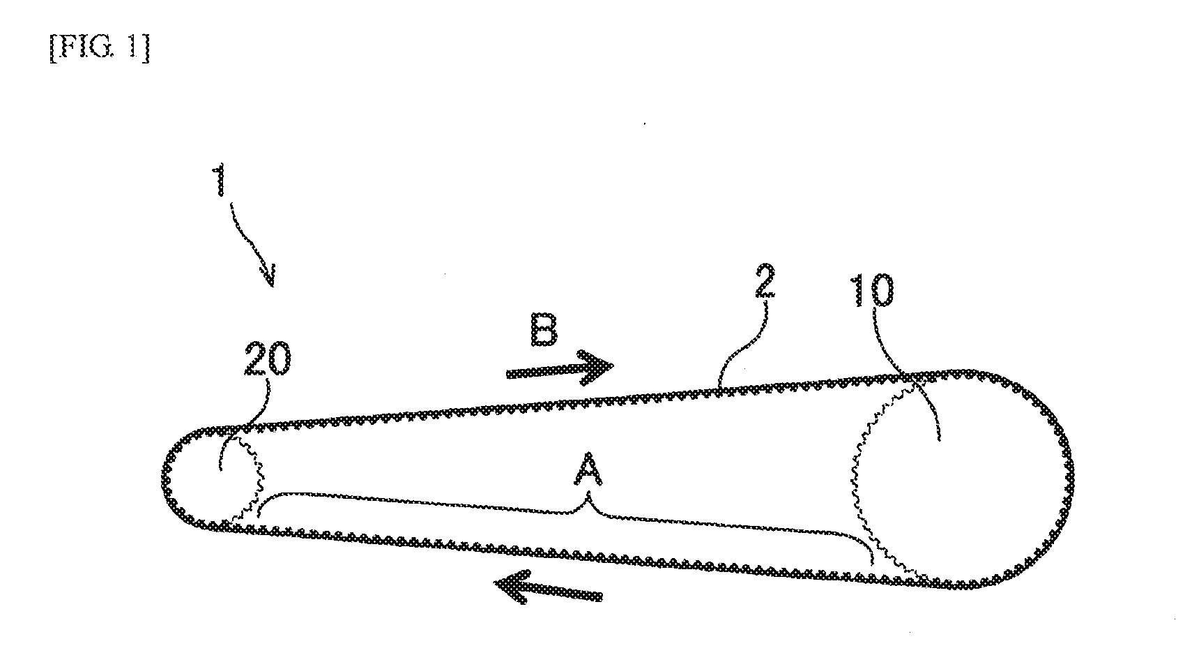
[0037]As illustrated in FIG. 1, a toothed belt driving device 1 for bicycle in this embodiment contains a drive pulley 10 connected to a rotational shaft of a pedal (not illustrated) of a bicycle; a driven pulley 20 connected to a rotational shaft of a rear wheel (not illustrated) of the bicycle; and an endless toothed belt 2 wrapped around the drive pulley 10 and the driven pulley 20. The toothed belt driving device 1 for bicycle in this embodiment does not have a tension adjustment mechanism that adjusts the tension of the toothed belt 2.
[0038]When a rider of the bicycle strokes the pedal and rotates the pedal, the drive pulley 10 rotates, a rotational motion thereof is transmitted to the driven pulley 20 through the toothed belt 2, and the rear wheel rotates.
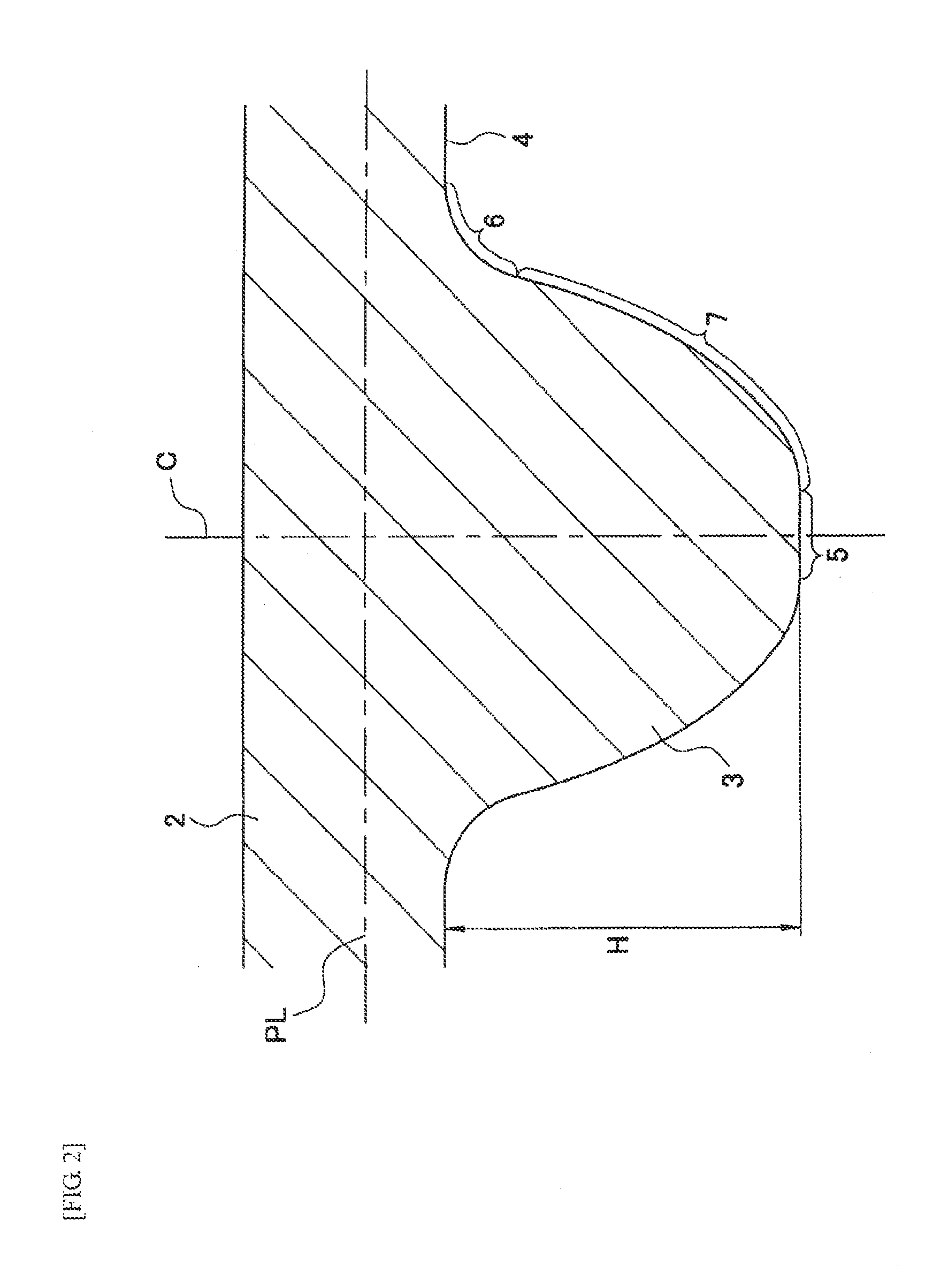
[0039]In the description below, a cross-section perpendicular to a width direction of the belt of the toothed belt dr...
second embodiment
[0068]Hereinafter, a second embodiment of the present invention will be described. For the same configuration elements as in the first embodiment is used the same reference signs and descriptions thereof will be appropriately omitted.
[0069]The toothed belt driving device for bicycle in this embodiment contains a driven pulley 120 different from the driven pulley 20 in the first embodiment, and the drive pulley 10 and the toothed belt 2 which are the same as in the first embodiment.
[0070]As illustrated in FIG. 7, pulley groove portions 121 are formed on an outer circumferential surface of the driven pulley 120 so as to mesh with the belt tooth portions 3. In FIG. 7, the driven pulley 20 in the first embodiment is illustrated by the dotted line. The outer diameter of the driven pulley 120 and the number of the pulley groove portions 121 are the same as those of the driven pulley 20 in the first embodiment.
[0071]In a side cross-section, the pulley groove portion 121 is formed asymmetri...
example 1
[0081]In Example 1, used were a drive pulley, a driven pulley and a toothed belt, which are the same as in the toothed belt driving device for bicycle according to the first embodiment illustrated in FIG. 1 to FIG. 6. The number of pulley groove portions of the drive pulley is 55, the number of the pulley groove portions of the driven pulley is 25, and a ratio in the number of grooves is 2.2. The drive pulley and the driven pulley are made of a steel material. The groove depth of the pulley groove portion of the drive pulley is 3.45 mm. The groove depth (Hp) of the pulley groove portion of the driven pulley is as shown in Table 1. The same drive pulley as in Example 1 was used as a drive pulley in each of Example 2 and Comparative Examples 2 to 8 which will be described later. The material and the number of grooves of pulley groove portions of the driven pulley used in Example 2 and Comparative Examples 2 to 8 which will be described later, are the same as that of the driven pulley ...
PUM
| Property | Measurement | Unit |
|---|---|---|
| Fraction | aaaaa | aaaaa |
| Fraction | aaaaa | aaaaa |
| Fraction | aaaaa | aaaaa |
Abstract
Description
Claims
Application Information
 - R&D
- Intellectual Property
- Life Sciences
- Materials
- Tech Scout
- Unparalleled Data Quality
- Higher Quality Content
- 60% Fewer Hallucinations
Browse by: Latest US Patents, China's latest patents, Technical Efficacy Thesaurus, Application Domain, Technology Topic, Popular Technical Reports.
© 2025 PatSnap. All rights reserved.Legal|Privacy policy|Modern Slavery Act Transparency Statement|Sitemap|About US| Contact US: help@patsnap.com