Gas sensor

a gas sensor and sensor technology, applied in the field of gas sensors, can solve the problems of not being able to perform the operation of attaching the gas sensor using the press-fitting method, which is expected to be easy, and the gas sensor is not easy to be twisted appropriately against rubber deformation, etc., to achieve suppressing slipping, large difference in contraction, and suppressing fingers. slipping

Inactive Publication Date: 2016-08-04
NGK SPARK PLUG CO LTD
View PDF15 Cites 5 Cited by
  • Summary
  • Abstract
  • Description
  • Claims
  • Application Information

AI Technical Summary

Benefits of technology

[0018]The vertical ribs may extend over the entire length of the outer peripheral surface of the cylindrical cover portion in the axial direction, may extend over a part of the length of the outer peripheral surface, or may be divided in the axial direction. The vertical ribs may be modified as long as they have the effect of suppressing slipping of fingers when an operator holds or grips the cylindrical cover portion and twists the cylindrical cover portion. The height to which the vertical ribs bulge (protrude) from the outer peripheral surface of the cylindrical cover portion, the width of the vertical ribs in the circumferential direction, and the number of the vertical ribs may be appropriately determined so that the effect of suppressing slipping can be obtained. Preferably, the height and the width of the vertical ribs are determined in consideration of the thickness and the like of parts of the cylindrical cover portion so that an excessively large difference in contraction may not occur when a molding resin is cooled to form the vertical ribs. Preferably, corners between the outer peripheral surface of the cylindrical cover portion and side surfaces of the vertical ribs, which bulge on the outer peripheral surface, are rounded as appropriate, and corners of the vertical ribs are chamfered as appropriate. By doing so, a die can be more reliably filled with a resin and the appearance of the cylindrical cover portion can be improved.
[0019]In the case where the gas sensor according to the present invention includes a metal tube as described above, the metal tube is embedded in the cylindrical cover portion of the protective cover by insert molding the protective cover by using the m

Problems solved by technology

Accordingly, in this operation, it is not possible to appropriately and smoothly attach the sensor by simply pressing the sensor straightly because the rubber packing (also referred to as the “rubber”) becomes deformed or twisted.
However, fingers of an operator tend to slip over the cylindrical cover portion (grip) of the protective cover of the existing gas sensor described above, because the cover portion is made of a resin and has a cylindrical outer peripheral surface.
Moreover, the existing gas sensor has a problem in that, although it is necessary to twist the gas sensor when press-fitting the gas sensor, it is not easy to twist the gas sensor appropriately against deformation of the rubber.
Therefore, it has been pointed out that the operation of attaching the gas sen

Method used


Image

  • Gas sensor
  • Gas sensor
  • Gas sensor

Examples


Embodiment Construction

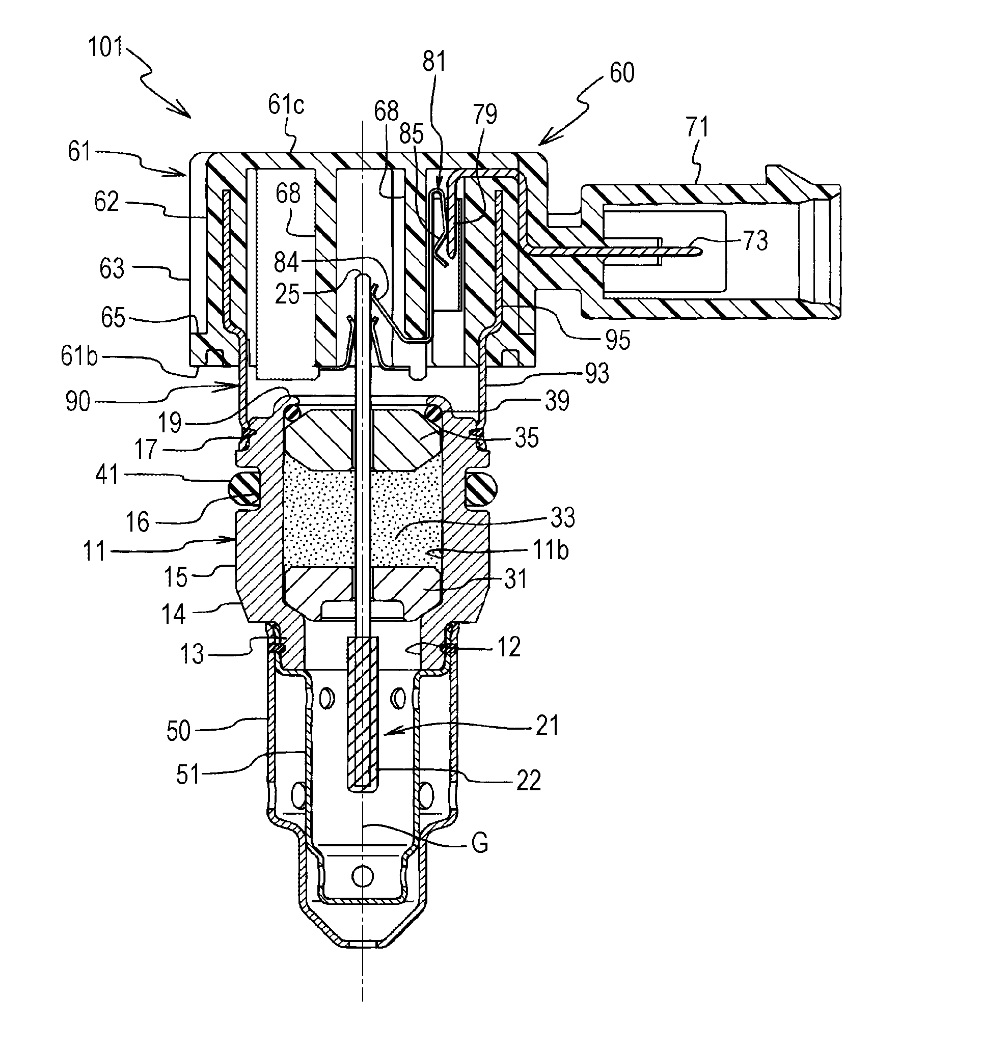
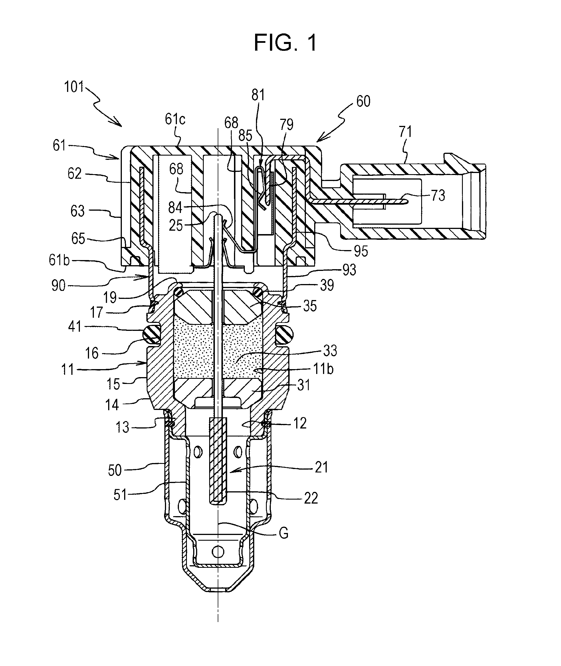
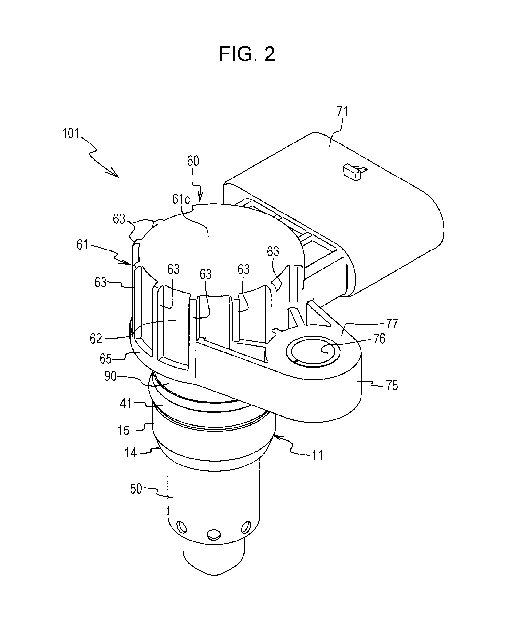
[0032]Referring to FIGS. 1 to 7, a gas sensor acceding to an embodiment of the present invention will be described in detail. The gas sensor according to the present embodiment is a wideband air-fuel ratio sensor for detecting the concentration of oxygen in a gas. As illustrated in FIG. 1, a gas sensor 101 includes a metal shell 11, a detection element 21, and a protective cover 60. The metal shell 11 (also referred to as a “shell 11”) has a tubular shape (stepped cylindrical shape). The detection element 21 is disposed in the metal shell 11, extends in the front-rear direction, and has a rear end 25 (see FIGS. 1 and 6) protruding rearward from the rear end (in FIG. 1, the upper end) of the shell 11. The protective cover 60 is fixed to the rear end of the shell 11 so as to cover the rear end 25 of the shell 11, and electrical connection means connected to the element 21, and the like. Hereinafter, these components will be described in detail.

[0033]An inner peripheral surface 11b of ...


PUM


Abstract

A gas sensor includes a protective cover having a resin cylindrical cover portion at a rear end thereof, that can be airtightly attached to an attachment hole, and that can prevent a decrease in quality and a molding defect. A plurality of vertical ribs, which extend substantially parallel to an axis of a cylindrical cover portion, are formed on an outer peripheral surface of the cylindrical cover portion so that protrusions and recesses are provided in a circumferential direction. Due to the presence of the vertical ribs, as compared with an existing cylindrical cover portion that has a smooth outer peripheral surface without the vertical ribs, defects of the outer peripheral surface are not likely to occur in a molding process. Moreover, because slipping is not likely to occur when an operator holds and twists the cylindrical cover portion with his/her fingers, an attachment operation can be smoothly performed.

Description

[0001]This application claims the benefit of Japanese Patent Applications No. 2015-016271, filed Jan. 30, 2015 and No. 2015-223121, filed Nov. 13, 2015, which are incorporated herein by reference in their entity.BACKGROUND OF THE INVENTION[0002]1. Field of the Invention[0003]The present invention relates to a gas sensor that is attached to an intake system (intake pipe or the like) or an exhaust system (exhaust pipe or the like) of an internal combustion engine, such as a diesel engine or a gasoline engine, and that is used to detect the concentration of a specific gas in a gas to be measured (detected), such as an intake gas or an exhaust gas.[0004]2. Description of the Related Art[0005]Gas sensors of this type include a detection element (also referred to as an “element”) having a strip-like shape or a bar-like shape (shaft-like shape). A front end portion of the element serves as a detection portion, and a pair of electrodes (detection electrodes) are disposed on the front end po...

Claims


Application Information

Patent Timeline
IPC IPC(8): G01N33/00G01M15/10
CPCG01M15/102G01N33/0009G01N27/4062G01N27/4077G01N27/4078
Inventor YONEZU, KUNIHIKOOBA, TAKEHIRO
Owner NGK SPARK PLUG CO LTD
Why Eureka
Try Eureka