Magnetic resonance device

a technology of magnetic resonance and standing wave trap, which is applied in the direction of measuring devices, magnetic measurements, instruments, etc., can solve the problems of labor-intensive and time-consuming manual production of standing wave traps, and achieve the effects of simplifying assembly and handling, simplifying component provision, and fast component placemen

Active Publication Date: 2016-08-04
SIEMENS HEALTHCARE GMBH
View PDF5 Cites 3 Cited by
  • Summary
  • Abstract
  • Description
  • Claims
  • Application Information

AI Technical Summary

Benefits of technology

[0036]According to a further embodiment, the at least one frequency filter is built using SMT components. The SMT components enable a particularly low-cost and fast component placement (including positioning and soldering).
[0037]According to yet a further embodiment, the section of the radiofrequency line that is routed through the B1 magnetic field is embodied on precisely ...

Problems solved by technology

A labor-intensive and time-consuming manual pro...

Method used


Image

  • Magnetic resonance device
  • Magnetic resonance device
  • Magnetic resonance device

Examples


Embodiment Construction

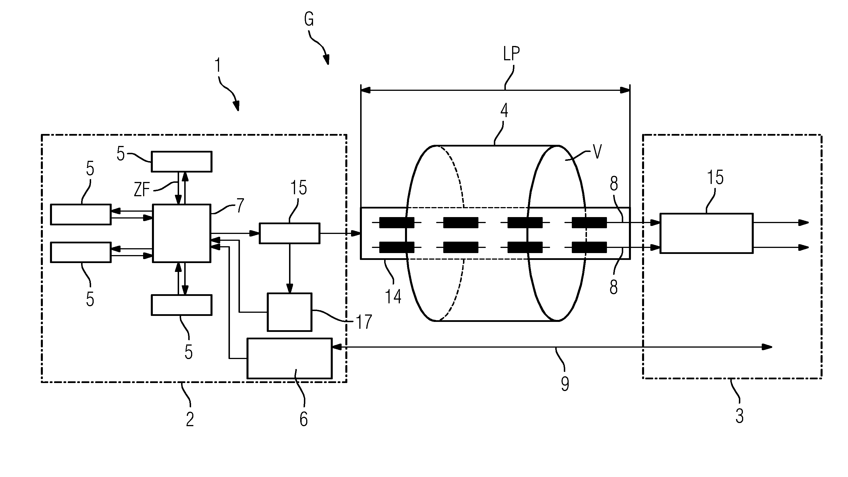
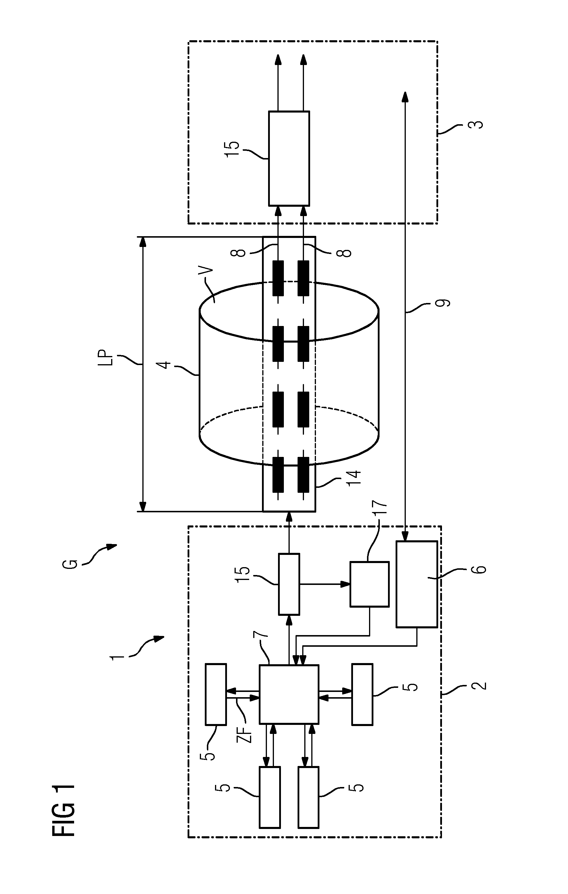
[0045]FIG. 1 shows a schematic diagram of a patient couch 1 of an MR device G. The patient couch 1 has a head end 2 and a foot end 3 between which a homogeneity volume V that may be generated by a body coil 4 (which does not constitute a part of the patient couch 1) is located. The homogeneity volume V corresponds at least approximately to a volume that is suitable for the MR measurement of a patient lying on the patient couch 1. The body coil 4 of the MR device G is, for example, stationary, while the patient couch 1 is mounted as displaceable with respect thereto.

[0046]The head end 2 has a plurality (e.g., four) of coil connectors or terminations 5 for connecting local coils (not shown). The terminations 5 also effect a frequency conversion of measurement signals received by the local coils to lower intermediate frequencies ZF. For this purpose, a local oscillator 6 that generates an auxiliary frequency for downmixing the original measurement signals at Larmor frequency to the int...


PUM


Abstract

An MR device includes at least one body coil for generating a B1 magnetic field and at least one radiofrequency line routed through the B1 magnetic field. The at least one radiofrequency line has at least one frequency filter for blocking a voltage induced by the B1 magnetic field. At least one section of the radiofrequency line routed through the B1 magnetic field is embodied in printed circuit board technology on at least one printed circuit board, and information-carrying signals may be transmitted over the at least one radiofrequency line on a different frequency than the frequency of the voltage induced by the B1 magnetic field.

Description

[0001]This application claims the benefit of DE 10 2015 201 963.2, filed on Feb. 4, 2015, which is hereby incorporated by reference in its entirety.BACKGROUND[0002]The present embodiments relate to a magnetic resonance (MR) device.[0003]In MR tomography as practiced today, images having a high signal-to-noise ratio (SNR) are generally acquired using “local coils” (e.g., “loops”). In this case, the excited nuclei of a measurement object induce a voltage in the local coils. The induced voltage is amplified by a low-noise preamplifier (LNA) and finally forwarded at the MR frequency via a cable connection to a receiver (e.g., receive electronics) of an MR receive system of an MR device.[0004]Powerful devices known as “high-field” systems are employed in order to improve the signal-to-noise ratio, including in the case of high-resolution images. The basic field strengths of such systems currently range up to 3 tesla (T) and higher. Since it is often possible to connect a greater number o...

Claims


Application Information

Patent Timeline
IPC IPC(8): G01R33/34G01R33/38
CPCG01R33/38G01R33/34046G01R33/3685
Inventor BIBER, STEPHANFACKELMEIER, ANDREASVESTER, MARKUS
Owner SIEMENS HEALTHCARE GMBH
Why Eureka
Try Eureka