
Few mode optical fibers for space division multiplexing

a technology of space division multiplexing and fiber optic fibers, applied in fiber transmission, electromagnetic transmission, transmission, etc., can solve the problems of reducing reducing the reach of the transmission system, and causing limits in the transmission system, so as to reduce the differential mode group delay and reduce the bend loss. , the effect of low leakage loss

Active Publication Date: 2016-08-04
DRAKA COMTEQ BV
View PDF2 Cites 13 Cited by
  • Summary
  • Abstract
  • Description
  • Claims
  • Application Information

AI Technical Summary

Benefits of technology

The patent describes a way to make a special type of fiber that can guide light with less loss. This can be accomplished by using a graded-index profile, which helps to match the speed of light with the fiber's structure. This graded-index profile can be designed to reduce problems with the speed of light in the fiber, making it easier to send optical signals through it with less loss. The patent also mentions that manufacturing this special fiber can be more challenging than other methods, but the graded-index profile allows for better optimization of the fiber's properties. Overall, this patent describes a way to make optical fibers that work better and are easier to manufacture.

Problems solved by technology

Although such designs are promising, they do not allow reducing the Differential Mode Group Delays as much as desired, and therefore induce limits in the transmission system reach.
In addition, the profiles disclosed in both documents are not optimized to ensure low bend losses and high leakage losses, which, however, are important issues for FMFs.
Actually, none of the known documents relating to FMFs addresses the issue of designing a few-mode fiber showing low bend losses and high leakage losses.

Method used


Image

  • Few mode optical fibers for space division multiplexing
  • Few mode optical fibers for space division multiplexing
  • Few mode optical fibers for space division multiplexing

Examples


first embodiment

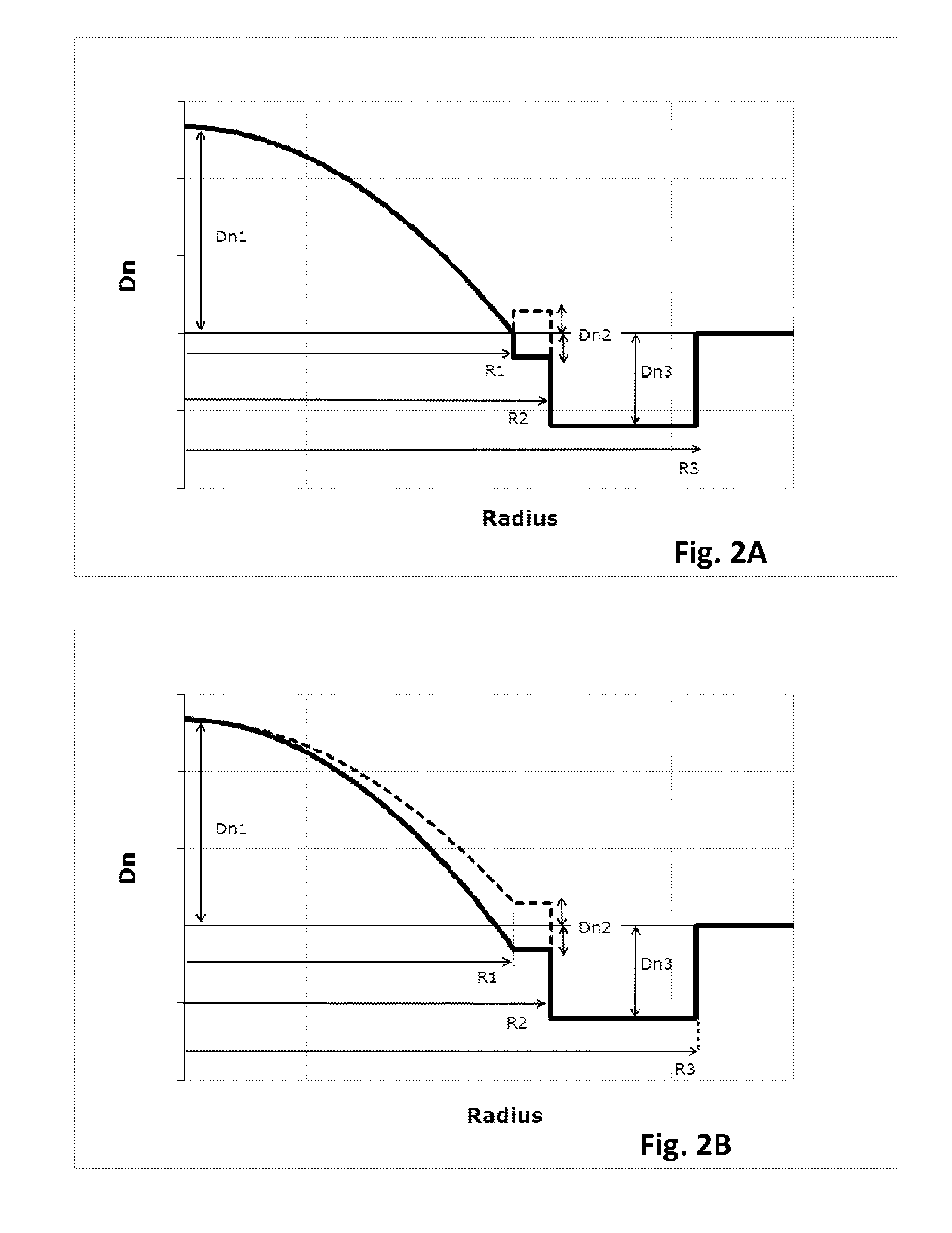
[0071]FIG. 2A depicts the refractive index profile n(r) of optical fiber 10 according to the invention. It describes the relationship between the refractive index value n and the distance r from the center of the optical fiber. The x-axis represents radial position with x=0 representing the center of the core region, and the y-axis represents refractive index, expressed as an index difference Dn unless otherwise stated.

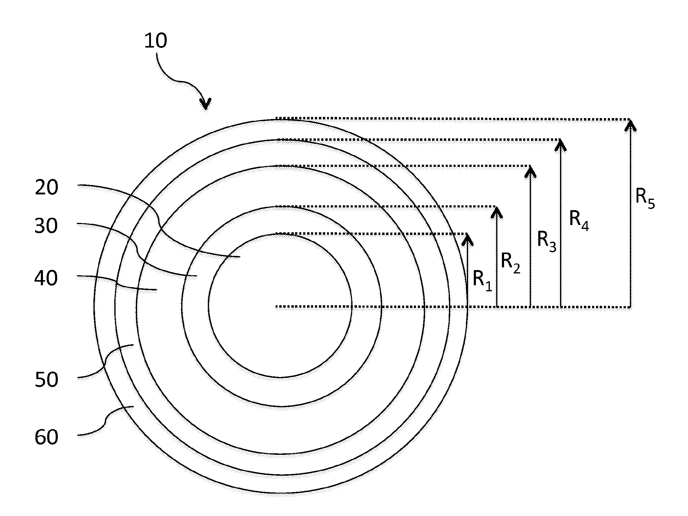
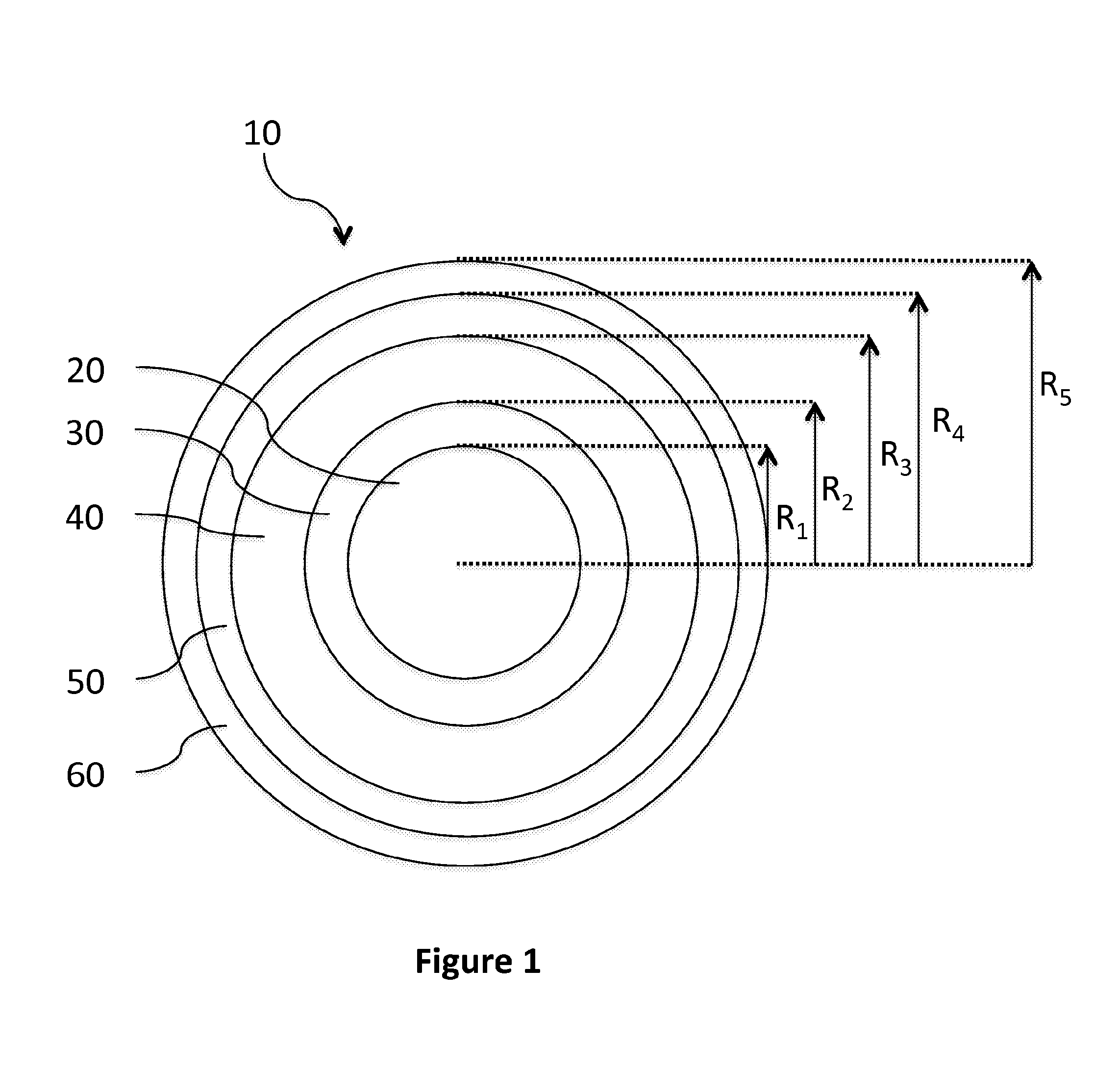
[0072]In that first embodiment, the optical fiber 10 has an optical core 20 having a refractive index profile n(r) defined as follows:

n(r)=n0·1-2·Δ·(rR1)αr≤R1

where:

r is a variable representative of the radius of the optical fiber,

R1 is the optical core radius,

Δ is the normalized refractive index difference, with

Δ=n02-n122n02

n1 is the minimal refractive index of the optical core,

n0 is the maximal refractive index of the optical core,

α is a non-dimensional parameter that defines the index profile shape of the optical core.

[0073]The alpha refractive index profile of the ...

third embodiment

[0086]FIG. 2C depicts the refractive index profile n(r) of an optical fiber according to the invention.

[0087]In this third embodiment, the inner cladding layer 30 is an extension of the graded index core 20, such that both the optical core 20 and the inner cladding layer 30 have a refractive index profile n(r) defined as follows:

n(r)=n0·1-2·Δ·(rR2)αr≤R2

where:

r is a variable representative of the radius of the optical fiber,

R2 is the outer radius of the inner cladding layer 30,

Δ is the normalized refractive index difference, with

Δ=n02-n122n02

n1 is the minimal refractive index of the inner cladding layer (i.e. the refractive index at radius R2),

n0 is the maximal refractive index of the optical core,

α is a non-dimensional parameter that defines the index profile shape of both the optical core and the inner cladding layer.

[0088]Hence, in this third embodiment, the term “single-α graded-index profile” has a slightly different meaning as compared to the first two embodiments, since this g...

second embodiment

[0111]FIG. 5 illustrates the evolution of Max|DMGD| as a function of wavelength for few-mode fibers supporting from 6 to 16 LP guided modes. More precisely, FIG. 5 shows the Max|DMGD| as a function of wavelength for Ex. 2, 5, 6 & 9 listed in Table 1. Such examples correspond to few-mode fiber according to the invention, as depicted in FIG. 2B.

[0112]The x-axis depicts the wavelength of the light guided by the fiber, ranging from 1530 to 1570 nm. The y-axis depicts the Max|DMGD| between any two LP guided modes, expressed as ps / km and ranging from 0 to 200. Curve 51 corresponds to the FMF guiding 6 LP modes of Example 2; curve 52 corresponds to the FMF guiding 9 LP modes of Example 5; curve 53 corresponds to the FMF guiding 12 LP modes of Example 6, while curve 54 corresponds to the FMF guiding 16 LP modes of Example 9.

[0113]As can be seen, the Max|DMGD| remains low in the entire extended C-band from 1530 to 1570 nm. The Max|DMGD| slope in this extended C-band is in absolute value <3 p...


PUM


Abstract

The invention relates to an optical fiber comprising an optical core and an optical cladding surrounding the optical core, the optical core having a single α graded-index profile with α≧1, and the optical core having a radius R1 and a maximal refractive index n0, said optical cladding having a refractive index nCl. Said optical cladding comprises a region of depressed refractive index ntrench, having an inner radius R2, with R2≧R1, and an outer radius R3, with R3>R2. According to embodiments of the invention, the α-value of said graded index profile and the optical core radius R1 are chosen such that R1≧13.5 μm and so as to satisfy a criterion C of quality. Thus, the invention provides a few-mode optical fiber, which allow guiding an increased number of LP modes as compared to prior art FMFs, while reaching the lowest Differential Mode Group Delay. The system reach is thus increased over prior art.

Description

1. FIELD OF THE INVENTION[0001]The invention relates to the field of fiber optic transmission, and, more specifically, to improved few-mode fiber designs for space division multiplexing.2. BACKGROUND[0002]An optical fiber is conventionally constituted of an optical core, which transmits an optical signal, and of an optical cladding, which confines the optical signal within the optical core. To that end the refractive index of the core, nc, is greater than the one of the cladding, nCl. An optical fiber is generally characterized by a refractive index profile that associates the refractive index (n) with the radius (r) of the optical fiber: the distance r with respect to the center of the optical fiber is shown on x-axis and the difference Dn between the refractive index at radius r, n(r), and the refractive index of the optical cladding nCl is shown on y-axis.[0003]Nowadays, two main categories of optical fibers exist: multimode fibers and single-mode fibers. In a multimode fiber, fo...

Claims


Application Information

Patent Timeline
IPC IPC(8): G02B6/028H04B10/25H04J14/00G02B6/036
CPCG02B6/02023G02B6/0288G02B6/03627H04J14/00H04J14/04H04B10/2504G02B6/0365H04J14/052H04J14/05H04B10/25891
Inventor SILLARD, PIERREMOLIN, DENISBIGOT-ASTRUC, MARIANNE
Owner DRAKA COMTEQ BV
Learn More