
Thin Optical Imaging module of a Biometric Apparatus

Active Publication Date: 2016-08-04
TRUE LIGHT
View PDF0 Cites 13 Cited by
  • Summary
  • Abstract
  • Description
  • Claims
  • Application Information

AI Technical Summary

Benefits of technology

The present invention provides a thin optical imaging module for a biometric apparatus that can capture both fingerprint and vein images simultaneously using a single image sensor. This is achieved by integrating an optical prism film and a glass substrate in the module, which reduces the overall volume and improves processing speed.

Problems solved by technology

On the other hand, a dual-mode biometric module, though reliable, faces a major problem in software integration.
Further, though the capacitor-type fingerprint sensor can be produced in a reduced volume, yet the distant client end would meet the following situations: (1) questionable reliability of the capacitor-type fingerprint sensor while is applied to face plural devices or systems, and (2) price hike upon the whole module due to the usage of the capacitor-type fingerprint sensors.

Method used


Image

  • Thin Optical Imaging module of a Biometric Apparatus
  • Thin Optical Imaging module of a Biometric Apparatus
  • Thin Optical Imaging module of a Biometric Apparatus

Examples


Embodiment Construction

[0027]The invention disclosed herein is directed to a thin optical imaging module of a biometric apparatus. In the following description, numerous details are set forth in order to provide a thorough understanding of the present invention. It will be appreciated by one skilled in the art that variations of these specific details are possible while still achieving the results of the present invention. In other instance, well-known components are not described in detail in order not to unnecessarily obscure the present invention.

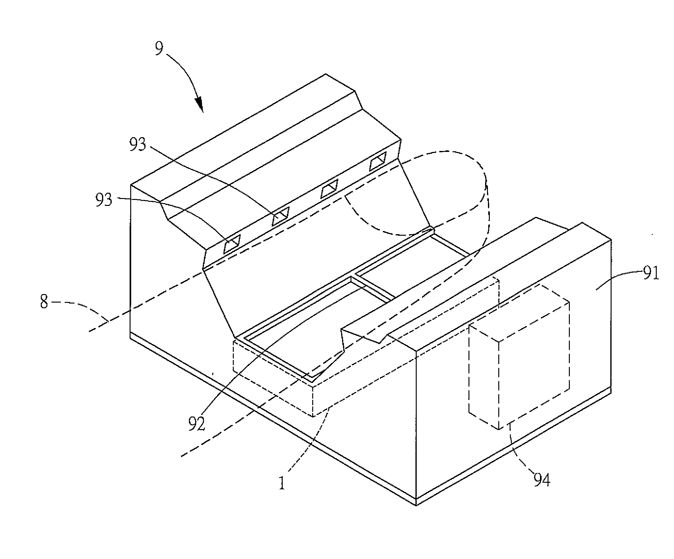
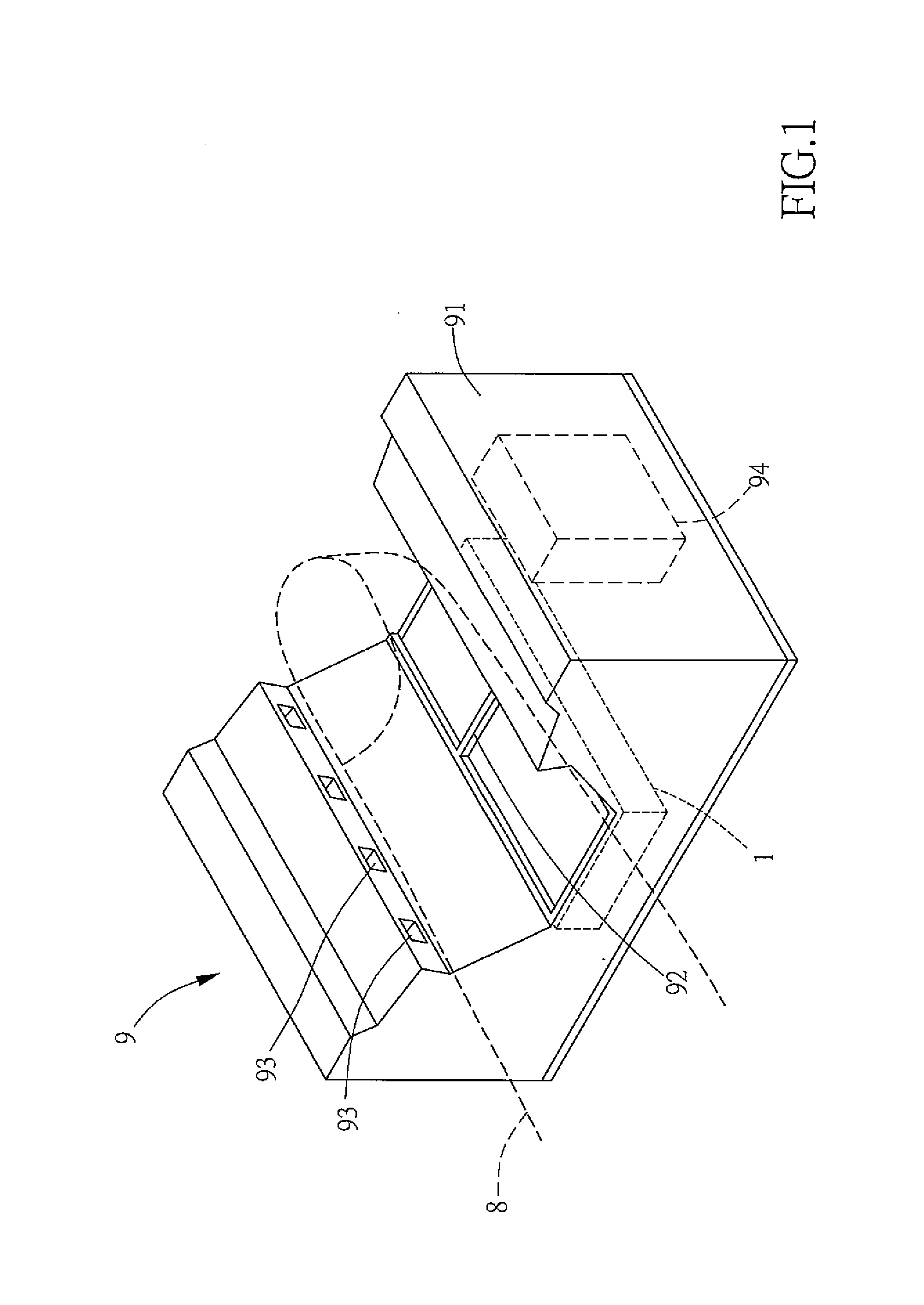
[0028]Referring now to FIG. 1, a schematic perspective view of a thin optical imaging module in accordance with the present invention mounted at a biometric apparatus is shown. The thin optical imaging module 1 of the present invention is mounted in the a biometric apparatus 9 for recognizing at least one biological characteristic. In the present invention, the term “biological characteristic” is specified as the “fingerprint” or the “vein”. The biometric appa...


PUM


Abstract

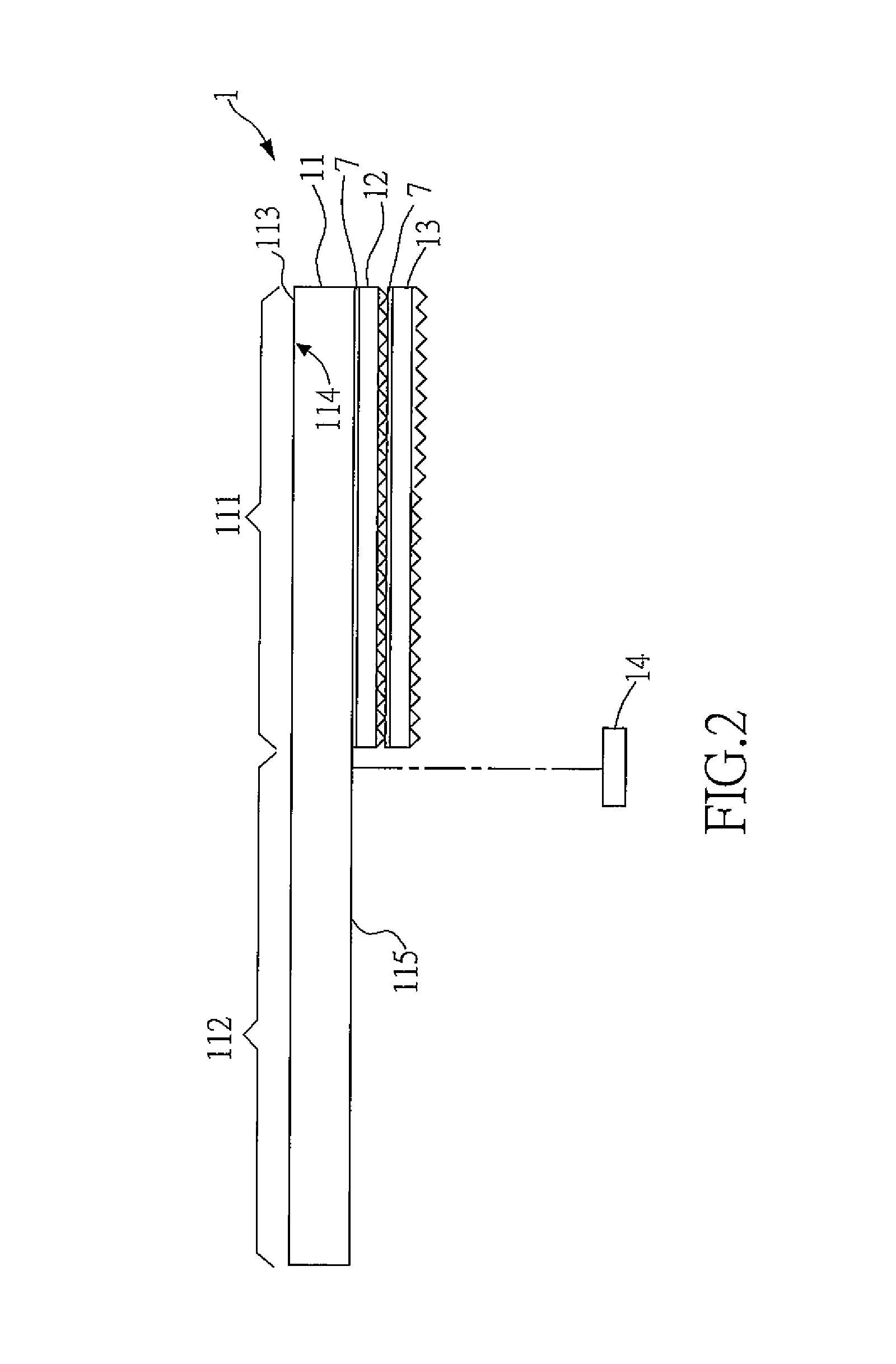
A thin optical imaging module of a biometric apparatus includes a first glass substrate, a first optical prism film, a second optical prism film, and an image sensor. The first glass substrate further includes a fingerprint imaging area, a vein imaging area, a contact surface, a reflective interface, and an attaching surface. The first optical prism film adhered to the attaching surface is located under the fingerprint imaging area. The second optical prism film is adhered to a position under the first optical prism film. The image sensor disposed in correspondence to the first glass substrate is located under the attaching surface.

Description

BACKGROUND OF INVENTION[0001]1. Field of the Invention[0002]The invention relates to a thin optical imaging module of a biometric apparatus, and more particularly to the thin optical imaging module that performs scanning upon the fingerprint and the vein so as to benefit the following verification, recognition or identification work.[0003]2. Description of the Prior Art[0004]To enhance the security level, assure the safety, and amend possible shortcomings in personal pin numbers, digital golden keys, built-in hardware golden keys of the smart chip and the like element for digital identification technology. Nowadays, more and more identity recognition and security systems have adopted or implemented with some kinds of biometric apparatuses. Among all these biometric apparatuses, the fingerprint identification device and the vein identification device are two of popular biometric apparatuses.[0005]On the other hand, a dual-mode biometric module, though reliable, faces a major problem ...

Claims


Application Information

Patent Timeline
IPC IPC(8): H04N5/225G02B5/04G02B27/00G06K9/00
CPCH04N5/2254G02B27/0025G02B5/045G06K9/00013G06V40/1324
Inventor CHANG CHIEN, CHIA CHINGCHEN, CHIH CHENGHUANG, ZHI KUEIPAN, JIN SHAN
Owner TRUE LIGHT
Learn More