
Rejection of the common-mode signal component in the measurement of bioelectric signals

a bioelectric signal and common-mode signal technology, applied in the field of differential voltage measuring system, can solve the problems of rare longer possible evaluation of ecg signal, attenuation of useful signal, and common-mode interference signal, and achieve the effect of eliminating differential components

Active Publication Date: 2016-08-11
SIEMENS HEALTHCARE GMBH
View PDF2 Cites 4 Cited by
  • Summary
  • Abstract
  • Description
  • Claims
  • Application Information

AI Technical Summary

Benefits of technology

The present invention is about improving a system for measuring electrical signals in humans. It introduces a method to measure interference signals that can affect the accuracy of the main signal being measured. By using a common potential for the measuring circuits, the system is effectively separated from the interference signals, providing a higher signal-to-noise ratio. The system also includes an amplifier circuit and a signal detection unit that can determine the average potential at different measurement points, eliminating differential components caused by the different quality of the electrode contacts. Overall, this invention results in a more reliable and accurate measure of electrical signals in humans.

Problems solved by technology

During the measurement of bioelectric signals, (e.g., of ECG signals), common-mode interference signals (e.g., interference as a result of common-mode signals) occur as a result of non-ideal measurement inputs of an ECG measuring arrangement.
In some instances, the differences in impedance at the inputs of the ECG measuring arrangement are even higher, such that an evaluation of the ECG signal scarcely appears to be possible any longer.
The shunt resistor influences the measurement signals detected by way of the amplifier circuit by thermal noise, however.
A problem with the arrangements described is that the adaptive filtering used therein also leads to an attenuation of the useful signal, which reduces the overall gain of the signal / noise ratio.

Method used


Image

  • Rejection of the common-mode signal component in the measurement of bioelectric signals
  • Rejection of the common-mode signal component in the measurement of bioelectric signals
  • Rejection of the common-mode signal component in the measurement of bioelectric signals

Examples


Embodiment Construction

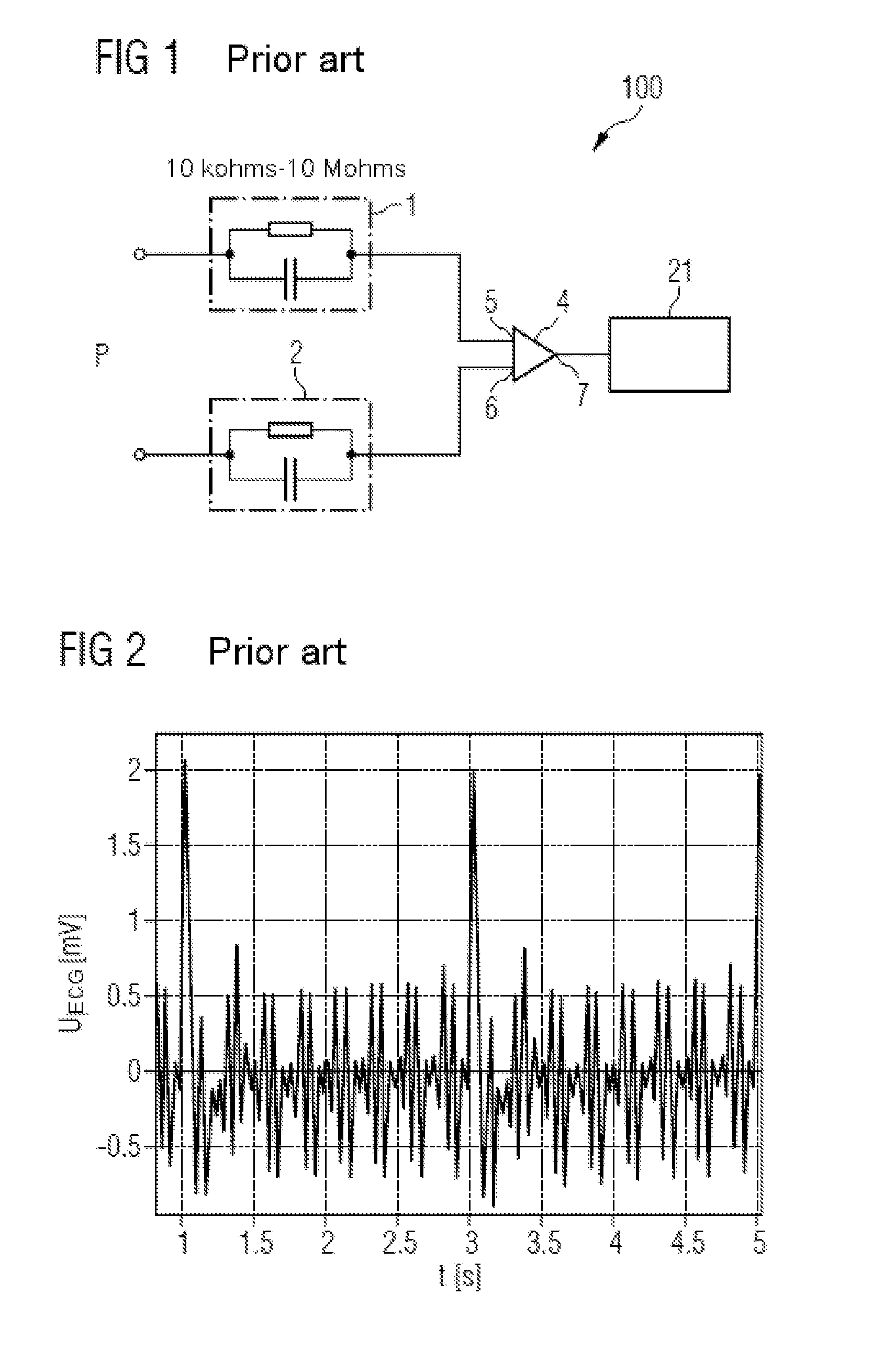
[0044]In FIG. 1, a conventional circuit arrangement 100 for measuring an electrocardiogram (ECG) of a patient P is depicted. The circuit arrangement 100 includes a first electrode 1 and a second electrode 2, which are in contact with the patient P in such a way that a cardiac current may flow by way of the electrodes 1, 2 to a differential amplifier 4. The amplifier 4 includes a first input 5, a second input 6 and an output 7. The first input 5 is electrically connected to the first electrode 1 and the second input 6 is electrically connected to the second electrode 2. The output signal of the amplifier 4 is transmitted to a signal detection unit 21, which detects the signal amplified by the amplifier 4. The two electrodes 1 and 2 are symbolized by an RC element, which illustrates the impedance values of the first measuring path and the second measuring path. In this case, the first measuring path runs from the contact of the first electrode 1 to the patient P by way of the first el...


PUM


Abstract

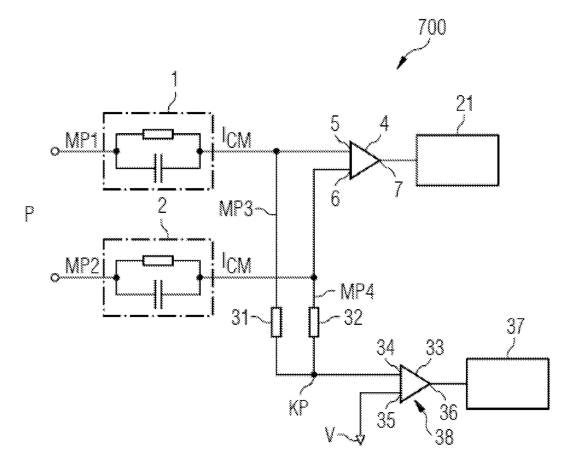
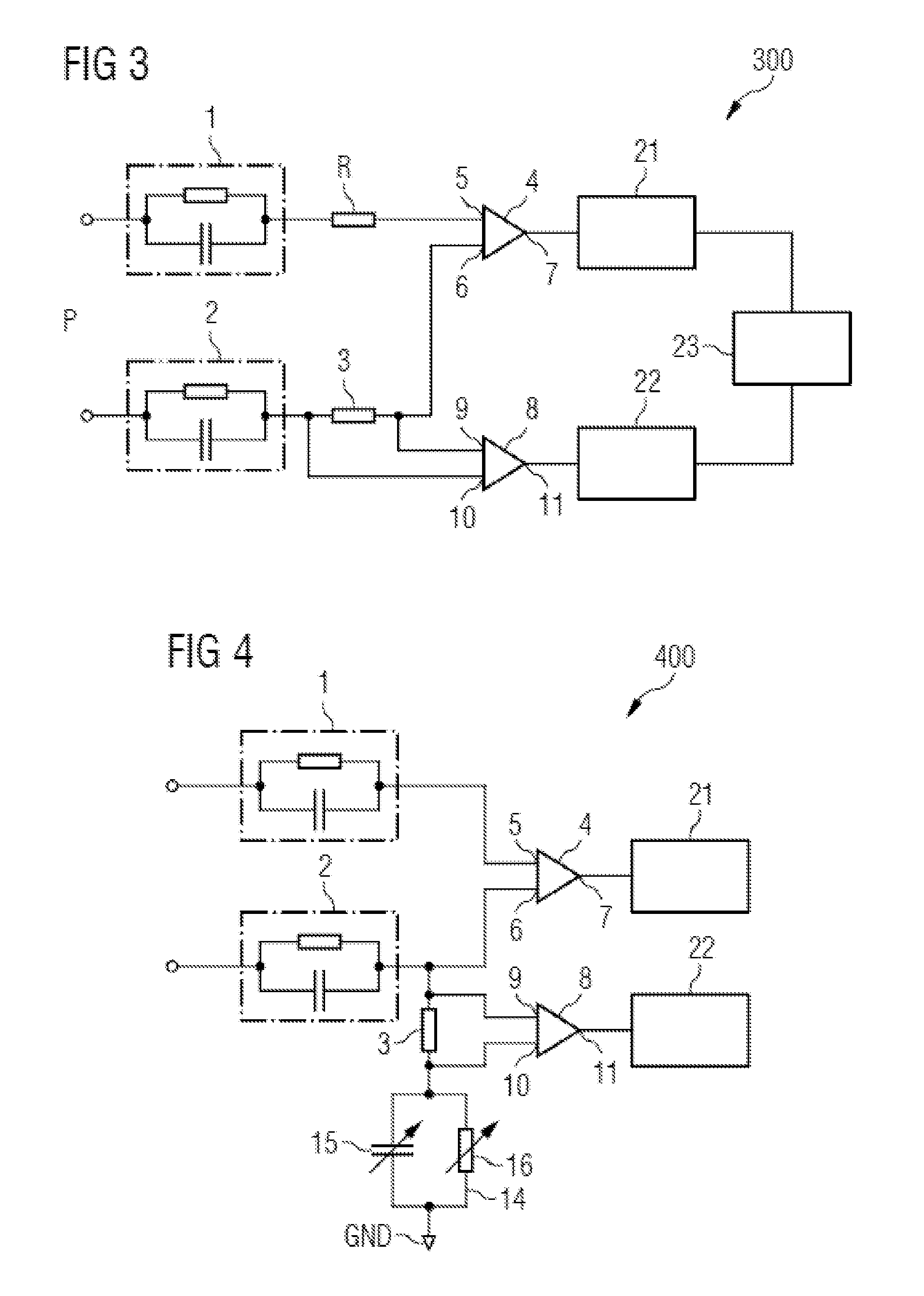
A differential voltage measuring system is described. The differential voltage measuring system has a signal measuring circuit for measuring bioelectric signals, and an interference-signal measuring circuit coupled to the potential of the differential voltage measuring system and electrically connected to a fixed reference potential. In this case, the interference-signal measuring circuit is designed for measuring a current flowing from the potential of the differential voltage measuring system to the fixed reference potential. A differential voltage measuring system with an additional path is also described. Furthermore, a differential voltage measuring system with an averaging potential measuring method is described.

Description

[0001]This application claims the benefit of DE 10 2015 202 447.4, filed on Feb. 11, 2015, which is hereby incorporated by reference in its entirety.TECHNICAL FIELD[0002]The embodiments relate to a differential voltage measuring system and to a method for differentially measuring voltages of bioelectric signals.BACKGROUND[0003]During the measurement of bioelectric signals, (e.g., of ECG signals), common-mode interference signals (e.g., interference as a result of common-mode signals) occur as a result of non-ideal measurement inputs of an ECG measuring arrangement. These signals arise, for example, from the power supply frequency at 50 Hz. Common-mode interference signals occur if non-identical conditions such as different impedances and capacitances occur at the two measurement inputs during the differential ECG signal measurement. An example of a conventional measuring arrangement for measuring an electrocardiogram is depicted in FIG. 1.[0004]Common-mode signals, (e.g., interferen...

Claims


Application Information

Patent Timeline
Patent Type & Authority Applications(United States)
IPC IPC(8): A61B5/0428A61B5/00G01R19/00A61B5/0408G01R17/00G01R15/14A61B5/308
CPCA61B5/0428G01R17/00A61B5/7203G01R19/0084A61B5/0408G01R15/146A61B5/053A61B5/318G01R19/10A61B5/25A61B5/30
Inventor BATZER, ULRICHGREIF, PETERKARL, HARALD
Owner SIEMENS HEALTHCARE GMBH
Learn More